Flat plate type two-stage centrifugal machine

A centrifuge and flat-plate technology, applied in centrifuges, centrifuges with rotating drums, etc., to eliminate resonance phenomena, improve quality and effect, and achieve good removal effects

Pending Publication Date: 2021-10-12
张家港阳旺机械有限公司
0 Cites 0 Cited by

AI-Extracted Technical Summary

Problems solved by technology

[0004] In order to solve the problems in the above-mentioned background technology, the object of the present invention is to provide a flat plate double-stage centrifuge, which realizes the double-stage separation of materials, improve...

Method used

During use, add material to be separated to the inside of the first filter screen 19 of the primary separation chamber 18 by feed pipe 12, the first filter screen 19 produces larger centrifugal force inside under the effect of the first driving device, in centrifugal force Under the action, it has a good pre-separation effect on the solid phase and liquid phase in the material, wherein the liquid phase in the material enters the second filter screen in the secondary separation chamber 22 through the first liquid discharge port 20 and the connecting pipe 21 23, the solid phase in the material adheres to the inside of the first filter 19 under the action of centrifugal force, and falls off to the bottom of the first filter 19 under the action of gravity, and the liquid phase in the material enters the inside of the second filter 23 Finally, deep separation treatment is carried out under the action of the second driving device. After two-stage continuous separation treatment, the liquid phase in the material is discharged through the second liquid discharge port 24 and the liquid discharge pipe 25, and the solid phase in the material adheres to the first Second, the inner side of the filter screen 23, under the action of its own gravity and the action of the jet pipe 35, the solid phase is removed from the filter screen and discharged through the discharge port. The removal effect is good and the quality of the solid phase material will not be damaged. 1. The shock absorbing device 2 is installed on the lower end surface, which effectively reduces the noise generated during the operation of the centrifuge and eliminates the resonance phenomenon generated during its operation.
Wherein, as shown in Figure 6, shock absorber 2 comprises top plate 3, base 8 and support column 5, and base 8 tops are provided with inverted trapezoidal groove, are fixedly provided with elastic element 9 in inverted trapezoidal groove, elastic element 9 The top is provided with a support column 5, the top of the support column 5 is fixed with a top plate 3, and the outer side of the support column 5 is provided with an an...

Abstract

The invention discloses a flat plate type two-stage centrifugal machine. The flat plate type two-stage centrifugal machine comprises a machine base, a machine shell, a partition plate, an upper cover and damping devices, the machine shell is fixedly arranged on the upper end face of the machine base, the four damping devices are arranged at the four corners of the lower end face of the machine base, the upper cover is arranged at an opening in the top of the machine shell, a feeding pipe is arranged on the upper cover, the partition plate is transversely and fixedly arranged in the machine shell, and the machine shell is divided into a first-stage separation chamber and a second-stage separation chamber; an inverted-cone-shaped first filter screen is arranged in the first-stage separation chamber, the first filter screen is connected with a first driving device used for driving the first filter screen to rotate, and a first liquid outlet is formed in the partition plate; and an inverted-cone-shaped second filter screen is arranged in the second-stage separation chamber and connected with a second driving device used for driving the second filter screen to rotate, a second feeding opening is formed in the top of the second filter screen, a connecting pipe is rotationally connected to the second feeding opening, the end, away from the second filter screen, of the connecting pipe communicates with the first liquid outlet, a second liquid outlet is formed in the bottom of the machine shell, and a liquid outlet pipe is arranged at the second liquid outlet.

Application Domain

Technology Topic

Image

  • Flat plate type two-stage centrifugal machine
  • Flat plate type two-stage centrifugal machine
  • Flat plate type two-stage centrifugal machine

Examples

  • Experimental program(1)

Example Embodiment

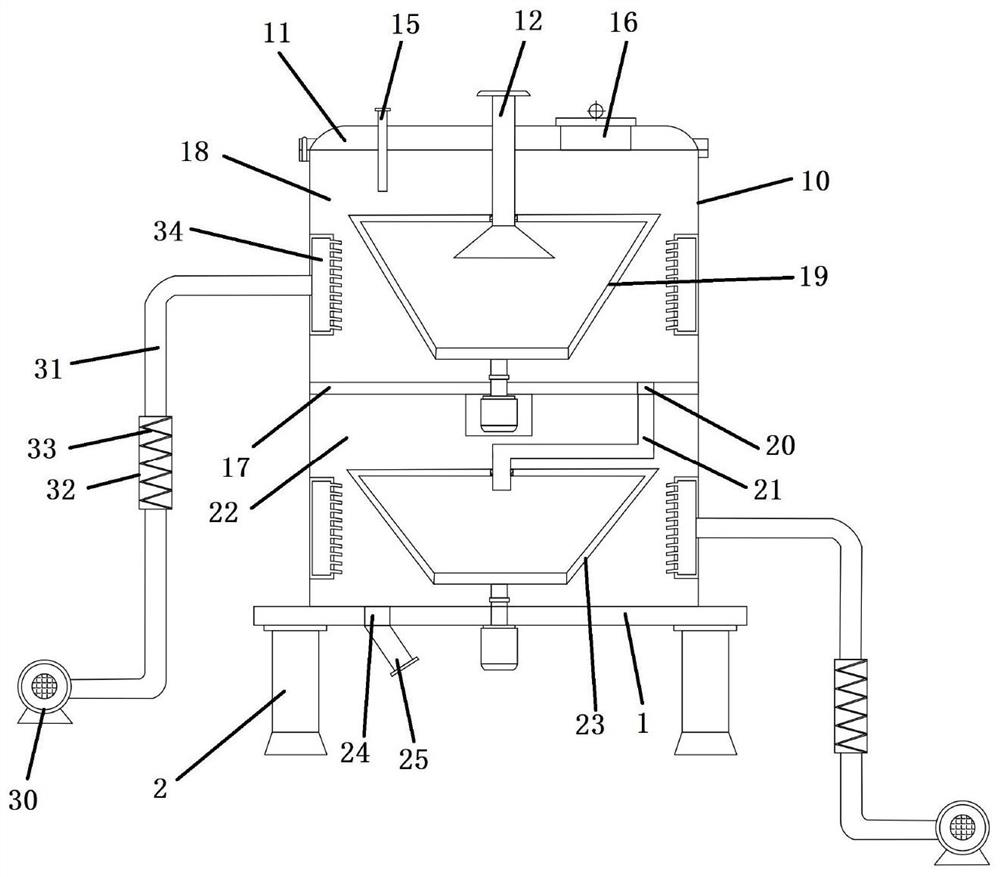
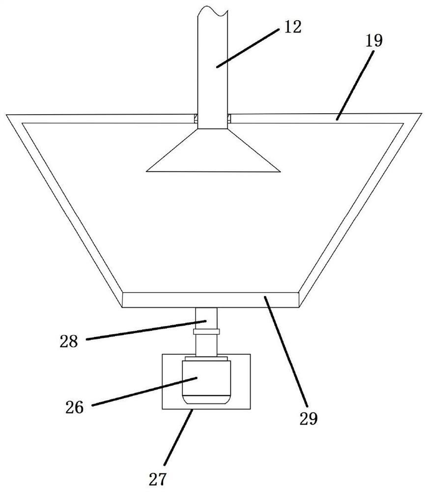
[0024] Embodiments of the present invention disclose a flat-type two-stage centrifuge, such as figure 2 As shown, including the seat 1, the casing 10, the separator plate 17, the upper cover 11, and the damper device 2, the casing 10 is fixedly disposed on the upper end surface of the seat 1, and four reductions are provided at the lower surface of the base 1. The shock device 2, the top opening of the casing 10 is provided with a sheet 11, and a feed tube 12 is provided on the upper cover 11, and the upper cover 11 is also provided with a washing tube 15 and a viewing hole 16, and the separator 17 is horizontally fixed. Inside the casing 10, it is divided into primary separation chamber 18 and the secondary separation chamber 22; the first-level separation chamber 18 is provided with a first filter 19, the first filter 19 and the driving thereof The rotating first drive is connected, and the first feed port is opened, and the lower end of the feed tube 12 is rotated to the first feed port and extend to the first filter 19, the partition plate 17 The first row of liquid port 20 is opened, and the first row of liquid port 20 is connected to the outer side of the first filter 19 and the inner side wall of the casing 10; the secondary separation chamber 22 is provided with a second filtration in parallel. Net 23, the second filter 23 is connected to the second driving device for driving its rotation, and the second feed port is opened at the top of the second filter 23, and the second feed opening is rotated and connected to the connection tube 21, the connecting tube 21 facing the second filter 23 is connected to the first row of liquid port 20, the pore size of the second filter 23 is smaller than the aperture of the first filter 19, and the casing 10 is opened at the bottom of the casing 10, and the second row. The liquid port 24 is in communication with the outer side of the second filter 23 and the inner side wall of the casing 10, and there is a discharge tube 25 at the second row of liquid, and two respective filtrations are opened on the casing 10. The interior of the network 19 and the unloading port in the second filter 23. In order to provide a support for the filter, the support plate can be fixed to the outer side of the first filter 19 and the second filter 23, and the through hole is uniformly opened on the support plate.
[0025] Among them, the first-stage separation chamber 18 and the inner side wall of the secondary separation chamber 22 are mounted in the circumferential direction, such as Figure 5As shown, the annular hollow structure has an annular hollow structure, and there is a plurality of air outlets in the inner side of the cyclic mold 34, and the jet direction is connected to the first filter 19 or the second filter 23. The jet 35, the outer side of the annular winding body 34 is opened, and the air outlet is in communication with the fan 30 located outside the casing 10 through the air blowing pipe 31. Through the fitting of the fan 30, the air supply pipe 31, the cyclic wind 34, the jet tube 35 can effectively remove the solid phase material in the inner adhesion of the first filter 19 and the second filter 23, and the effect is good, and Avoid using a wiper apparatus, extend the service life of the first filter 19 and the second filter 23. A heating tube 32 is also provided on the air supply tube 31, and the heating box 32 is provided with an electric heating wire 33 having a folded structure. The electric heating wire 33 in the heating tank 32 can enter the airflow from the fan 30 to the air supply pipe 31. The heating is performed, and the spray tube 35 is sprayed to the first filter network 19 and the second filtering web 23, and the solid phase material in the inside of the filter is dried, and the moisture content of the solid phase material is reduced. The material is removed from the filter.
[0026] Among them, if image 3 As shown in the configuration, the first driving device and the second drive device are the same, the first driving device includes a drive motor 26, a rotating shaft 28, and a rotating disk 29, and the drive motor 26 is fixedly disposed at the lower end surface of the partition plate 17, and the rotating shaft 28 is located at level 1. Inside the separation chamber 18, the upper end of the rotating shaft 28 is fixedly provided with the rotating disk 29, and the lower end of the rotating shaft 28 is connected to the driving motor 26, and the lower end of the first filter 19 is fixed to the rotating disk 29, and the driving motor 26 is provided with a waterproof protective case 27. When used, the first driving device and the second driving device can be controlled in opposite to the rotation direction of the second filter 23, such that the material is subjected to centrifugal force within the primary separation chamber 18 and the secondary separation chamber 22. Different motion trajectories, increase the separation effect of the material.
[0027] Among them, if Figure 4 As shown, the feed tube 12 is located at one end of the first filter 19, and there is a baffle 13 in the flap shape, and the outer side of the baffle 13 and the first feed tube 12 is inside the outer side. Phase connection, the inner side of the feed tube 12 and the outer side of the baffle 13 form a gap passed. When used, the material enters into the first filter 19 in the slit formed from the outer side of the baffle 13 in the inside of the baffle 12, such a feed mode, enters the material to the first filter from the feed tube 12 to the first filter. Inside.
[0028] Among them, if Image 6 As shown, the damper device 2 includes a top plate 3, a base 8, and a support post 5. The top of the base 8 is opened, and an elastic member is fixed inverted inverted inverted groove, and the elastic member 9 is provided with a support post 5. The top of the support column 5 is fixedly provided with a top plate 3, and the outer sleeve of the support post 5 is provided with a space-shaped metal plate 6 and a cyclic elastic plate 7, and the top plate 3 is uniformly opened with a plurality of mounting holes 4, elastic members 9 and The annular elastic plate 7 is a rubber material. By setting the shock absorber 2, the noise generated by the centrifuge is effectively reduced, and the resonance phenomenon generated at the time of operation is eliminated, and the mounting hole 4 is provided on the top plate 3 to facilitate mounting the damping device 2. Block 1.
[0029] When used, the material to be separated from the first filter 19 of the primary separation chamber 18 is added to the first filter 19 of the primary separation chamber 18, and the first filter 19 generates a larger centrifugal force inside the first driving device, and under the action of centrifugation. The solid phase and the liquid phase in the material are a well-separated effect, in which the liquid phase in the material enters the second filter 23 in the secondary separation chamber 22 through the first row of liquid port 20 and the connecting pipe 21, The solid phase in the material is adhered to the inside of the first filter 19 under the action of centrifugation, and the bottom of the first filter 19 is detached to the bottom of the first filter 19, and the liquid phase in the material enters the second filter 23, The depth separation treatment is performed under the action of the second driving device, and the liquid phase in the material is discharged through the second row of liquid inlet 24 and the discharge tube 25 after two stage continuous separation treatment, and the solid phase adhesion in the material is in the second filter. On the inside of 23, under the action of its own gravity and the jet 35, the solid phase is detached from the filter, and the elimination port is discharged, the effect is good, and the quality of the solid phase material is not destroyed. Set the damper device 2, effectively reduces the noise generated by the centrifuge operation, and eliminates the resonance phenomenon generated at the time of operation.
[0030] Specific examples are described above, and the present invention is applied, but is intended to help understand the invention and is not intended to limit the invention. For those skilled in the art of the present invention, several simple deceptions, deformations, or replacement can be made in accordance with the idea of ​​the present invention.

PUM

no PUM

Description & Claims & Application Information

We can also present the details of the Description, Claims and Application information to help users get a comprehensive understanding of the technical details of the patent, such as background art, summary of invention, brief description of drawings, description of embodiments, and other original content. On the other hand, users can also determine the specific scope of protection of the technology through the list of claims; as well as understand the changes in the life cycle of the technology with the presentation of the patent timeline. Login to view more.

Similar technology patents

Classification and recommendation of technical efficacy words

  • Improve quality and performance
  • Good removal effect

Quenching process of H13 steel aluminum alloy die-casting die

InactiveCN106755880AThe quenching process is simpleImprove quality and performanceFurnace typesHeat treatment furnacesQuenchingStress relief
Owner:巴南区伟鹏机械加工厂

Impact filtering method for strengthening asymmetric binary modulating signal

ActiveCN101599754AGood removal effectPreserve or even highlight signal modulation featuresDigital technique networkSignal-to-noise ratio (imaging)Wave shape
Owner:苏州东奇信息科技股份有限公司
Why Eureka
Try Eureka