Coiled tubing suspension device, coiled tubing wellhead mandrel type suspension structure and method

A suspension device and coiled tubing technology, used in earth-moving drilling, wellbore/well components, sealing/packaging, etc., can solve problems such as unfavorable normal operation of workers, inability to close the main valve of the wellhead, and increase the height of the wellhead, etc. The effect of avoiding restoration costs and hot work, being suitable for widespread use, and reducing operating costs

Pending Publication Date: 2021-10-12
BC P INC CHINA NAT PETROLEUM CORP +3
View PDF12 Cites 3 Cited by
  • Summary
  • Abstract
  • Description
  • Claims
  • Application Information

AI Technical Summary

Problems solved by technology

[0003] In recent years, gas well coiled tubing usually adopts a special wellhead slip suspension device to suspend the coiled tubing above the main production valve at the wellhead. However, this suspension completion method requires additional Adding hardware facilities such as special suspension devices and gate valves requires high supporting costs, and requires major changes to the existing production process. After the construction is completed, the main valve at the wellhead cannot be closed, resulting in idle waste and increasing the cost of the wellhead. The height is not conducive to the normal operation of the staff at the wellhead
[0004] Aiming at the problems in the related art that the suspension device for suspension of gas well coiled tubing has complex structure, inconvenient wellhead operation, and high supporting costs, no effective solution has been given so far

Method used


Image

  • Coiled tubing suspension device, coiled tubing wellhead mandrel type suspension structure and method
  • Coiled tubing suspension device, coiled tubing wellhead mandrel type suspension structure and method
  • Coiled tubing suspension device, coiled tubing wellhead mandrel type suspension structure and method

Examples


Embodiment 1

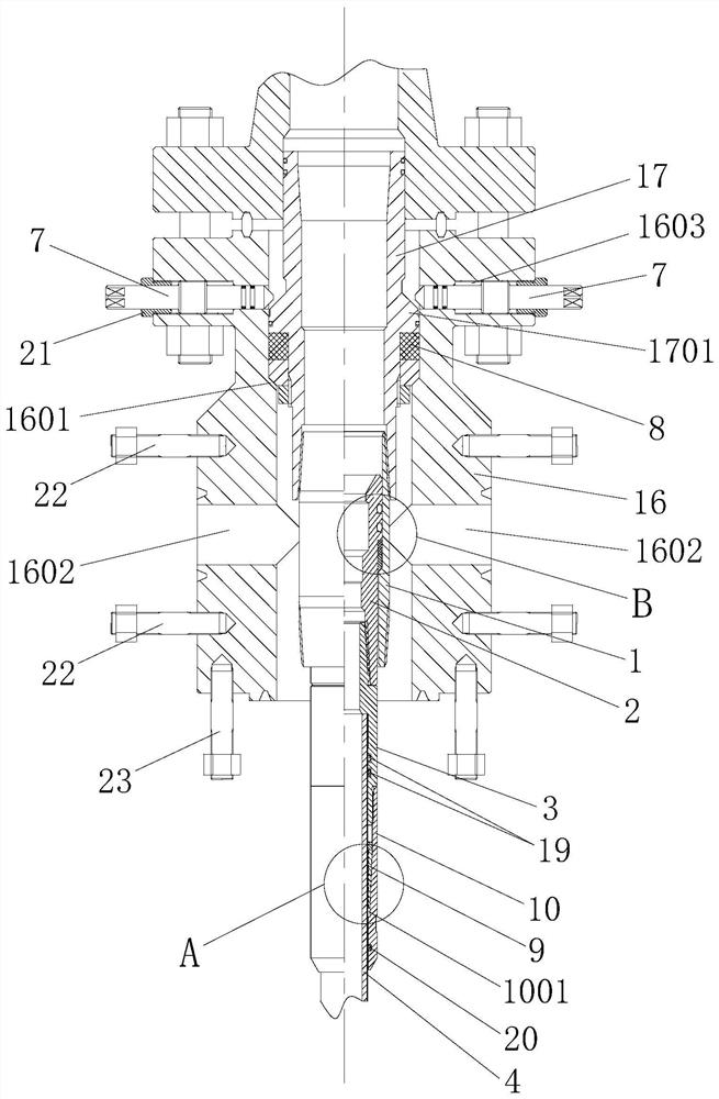
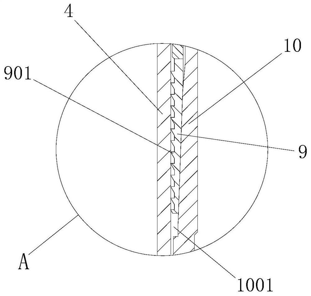
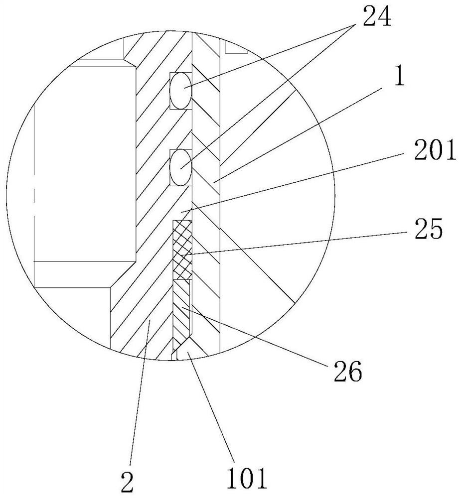
[0074] like Figure 1 to 3 , Figure 5 As shown, the present invention provides a continuous tube suspension, which is disposed at the wellhead, and the top of the continuous tube suspension is connected to the wellhead, which is connected to the continuous tube 4. The continuous tube suspension includes a tubing head 16, a tubing 17, a heavy load connector 3, and a lower joint 10. The tubing head 16 is a vertical arrangement of a cylindrical structure, and the tube hanging 17 is disposed inside the tubing head 16, the tube hanging 17, the overload connector 3 and the lower joint 10 are arranged in the upper to the lower order, and the bottom portion of the tube hanging 17 is connected between the top of the heavy load connector 3 or the bottom and overload connection of the tube hanging 17. A hanging short section 1 and the seat short section 2 are connected between the top to bottom, and the bottom of the heavy-load connector 3 is connected, and the overload connector 3 and the lo...

Embodiment 2

[0094] like Figure 4 , Image 6 As shown, the present invention provides a continuous tube well port core shaft-shaped suspension structure including injection head 11, a spray assembly 27, a wellhead main valve 15, and a continuous tube suspension device, injection Head 11, spray assembly 27, wellhead main valve 15 and the above-described continuous tube suspension device are all disposed above the wellhead. Among them: The bottom portion of the continuous tube suspension device is fixed at the wellhead, and the continuous tube 4 connected to the continuous tube suspension is incorporated into the well-in-well preset position, and the bottom of the main valve 15 of the wellhead is connected to the top of the continuous pipe suspension device, the main opening The top portion of the valve 15 is connected to the bottom of the spray assembly 27, and the top portion of the spray assembly 27 is connected to the bottom of the injection head 11.

[0095] In an alternative embodiment of t...

Embodiment 3

[0101] like Figure 1 to 6 As shown, the present invention provides a continuous tube well port core shaft suspension method including the following steps:

[0102] Step S1: The injection head 11, the spray assembly 27, the well port main valve 15, and the tubing head 16 are connected in the wellhead, and the main valve 15 opens the joint main valve to the continuous pipe 4 into the well preset position, continuous tube 4 is fixed at the well.

[0103] Step S2: Start the spray assembly 27 to seal to the ring air between the continuous pipe 4 and the wellhead;

[0104] Step S3: The overload connector 3 is connected at the top end of the continuous tube 4, and the feed tool is installed at the bottom of the injection head 11;

[0105] Step S4: Turn off the spray assembly 27, slow down the continuous tube 4 by the injection head 11 and the feed tool, and secure the top end of the continuous tube 4 in the tubing head 16;

[0106] Step S5: The end 11 is submitted to remove the feed tool...


PUM


Abstract

The invention relates to a coiled tubing suspension device and a coiled tubing wellhead mandrel type suspension structure and method. The coiled tubing suspension device comprises a tubing head, a tubing hanger, a heavy load connector and a lower connector, wherein the tubing hanger is arranged in the tubing head, the tubing hanger, the heavy load connector and the lower connector are sequentially arranged from top to bottom, an adapter pup joint is connected between the bottom of the tubing hanger and the top of the heavy load connector or a suspension pup joint and a setting pup joint are sequentially connected from top to bottom, the bottom of the heavy load connector is connected with the top of the lower connector, the heavy load connector and the lower connector both sleeve the outer side of the top of a coiled tubing, and a locking ring is arranged between the lower connector and the coiled tubing; the outer wall of the locking ring is slidably connected with the inner wall of the lower connector, and the inner wall of the locking ring abuts against the outer wall of the coiled tubing. According to the coiled tubing suspension device, the technical problems that a suspension device for suspending the gas well coiled tubing is complex in structure, wellhead operation is inconvenient, and the matching cost is high are solved.

Description

Technical field [0001] The present invention relates to the inventive field of gas well production, and in particular, to a continuous tube suspension device, a continuous pipe well port core shaft type suspension structure and method. Background technique [0002] At present, the gas well completion is usually used under pressure well conditions, and the matting operation is large to the ground damage, affecting the production of gas well, and uses a pressure-working device to enter the conventional oil pipe, although it avoids the pressure, but there is also a job Fees, high construction efficiency. Using continuous tubes instead of the routine single tube column as the finishing pillar, the whole process pressure is realized, avoiding the risk of maturing damage stratum and dysfunction, improving the production of single well production and reserves, realization Efficient and low cost operation. With the continuous increase in oil gas well, the number of oil gaves, and the con...

Claims


Application Information

Patent Timeline
Patent Type & Authority Applications(China)
IPC IPC(8): E21B33/04E21B33/06
CPCE21B33/04E21B33/0422E21B33/06
Inventor 胡强法朱峰吕维平付悦盖志亮贾夏刘习雄
Owner BC P INC CHINA NAT PETROLEUM CORP
Why Eureka
Try Eureka