Valve control device

A valve control and valve technology, applied in the field of valve control devices, can solve problems such as safety accidents, pipeline transformation, and complex transformation processes

Pending Publication Date: 2021-10-12
HANGZHOU GREAT STAR IND CO LTD
View PDF0 Cites 3 Cited by
  • Summary
  • Abstract
  • Description
  • Claims
  • Application Information

AI Technical Summary

Problems solved by technology

For families using manual valves, if there is no one at home, if water leakage or air leakage occurs, it will cause damage to the property in the home, and may lead to safety accidents in severe cases.
However, replacing manual valves with electric valves requires not only the purchase of electric valves, but also the need to modify the pipeline, which is costly and complicated.

Method used


Image

  • Valve control device
  • Valve control device
  • Valve control device

Examples


Embodiment 1

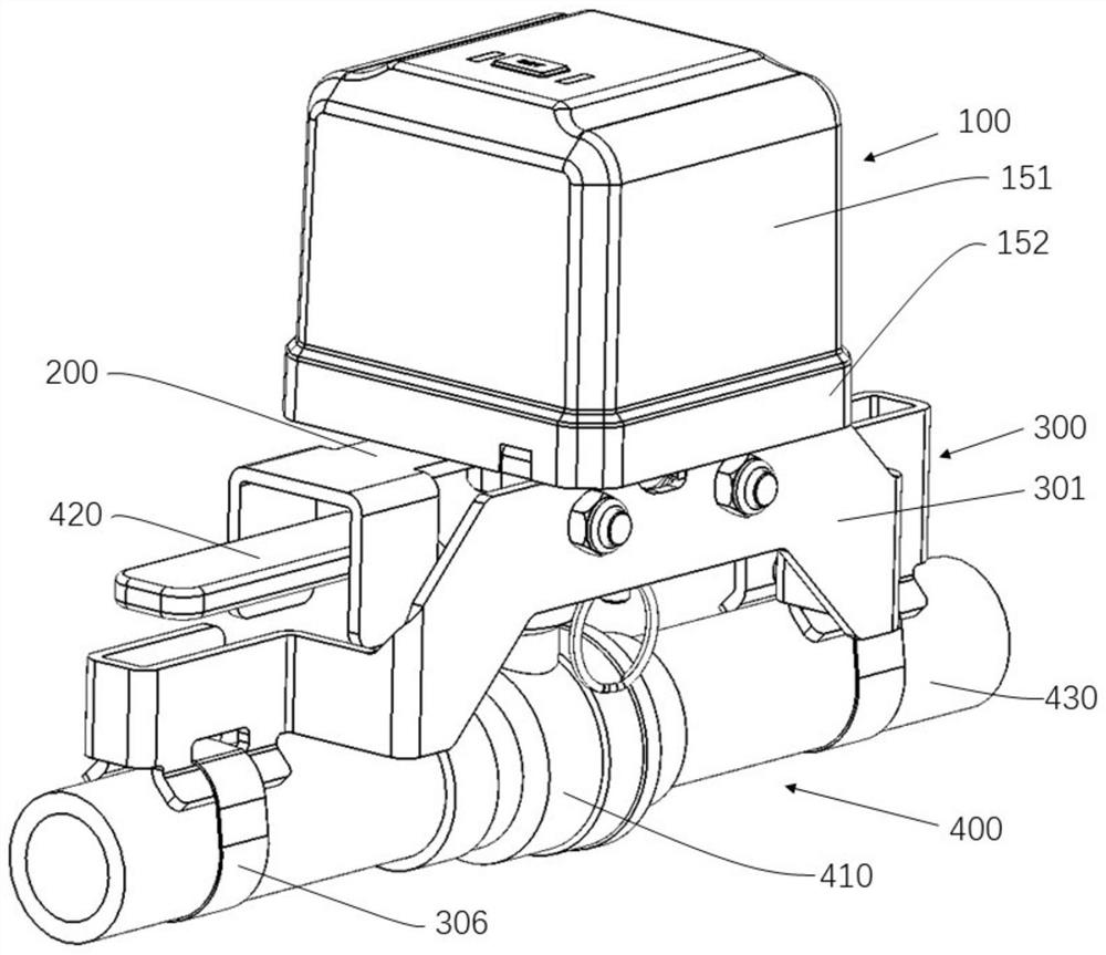
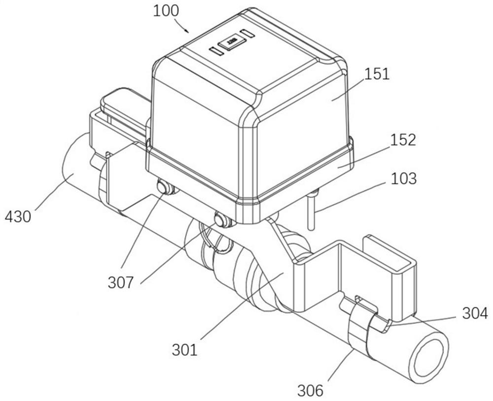
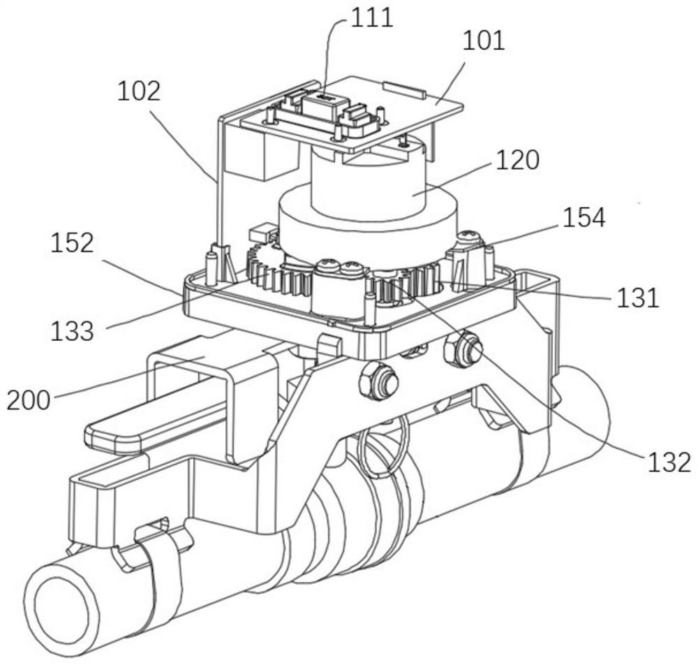
[0084] Such as figure 1 and figure 2 As shown, this embodiment provides a valve control device, including a control unit 100 , a first actuator 200 and a fixing mechanism 300 . The first actuator 200 is connected to the control part 100 , the control part 100 is fixed on the fixing mechanism 300 , and the fixing mechanism 300 is fixed on the valve assembly 400 . Wherein, the valve assembly 400 is an existing structure, including a valve 410, a handle 420 for controlling the valve 410, and a pipeline 430 connected to the valve 410. The pipeline 430 can be a pipeline for allowing water or gas to flow through. By manually rotating the handle 420 , the valve 410 can be opened and / or closed. The first actuator 200 is attached to the handle 420 , and the control unit 100 can control the movement of the first actuator 200 according to the received signal, and then the first actuator 200 drives the handle 420 to automatically open or close the valve 410 . The control part 100 and ...

Embodiment 2

[0109] Figure 15-Figure 20 Example 2 is shown. Compared with Embodiment 1, this embodiment differs only in the structure in which the actuator is attached to the handle 420 and the structure in which the bracket is fixed to the pipe 430 . Therefore, only the differences from Embodiment 1 will be described here.

[0110] In Embodiment 1, the first actuator 200 can only be attached to a handle of a specific size, and cannot be adapted to handles of different sizes. In order to solve this problem, in this embodiment, an adjustment mechanism is provided on the second actuator 210 . The adjustment mechanism includes a locking portion 213 , a first sliding block 215 and a second sliding block 225 . The first sliding block 215 is "L"-shaped, including a first sliding portion 216 and a first blocking portion 217, and a first slide groove 218 is obliquely arranged on the first sliding portion 216; A sliding blocking piece 215 has a similar structure, including a second sliding portio...

Embodiment 3

[0113] Figure 21 and Figure 22 Embodiment 3 is shown, compared with embodiment 1, the difference is only in the structure of the attachment of the actuator to the handle 420 .

[0114] Such as Figure 21 As shown, the fixing mechanism 300 includes a third bracket 331 and a fastening seat 340 separated from the third bracket 331 . Both ends of the third bracket 331 are respectively provided with second fixing parts, specifically, the second fixing parts of the third bracket 331 are configured as inserting pieces 332 . The fastening seat 340 includes a fourth “V”-shaped fastening surface 341 fitted with the pipe 430 , a through hole for passing through the second fastening belt 343 , and a slot 342 for inserting the insertion piece 332 . During installation, two identical fastening seats 340 are respectively fastened on the pipe 430 through the second fastening belt 343, and the positions of the two fastening seats 340 are corresponding to the two insertion pieces 332 of th...


PUM


Abstract

The invention discloses a valve control device. The valve control device comprises a driving unit, an executing mechanism and a control module; the executing mechanism is connected with the driving unit through a transmission mechanism and is attached to a valve; the executing mechanism is configured to be capable of moving under driving of the driving unit so as to drive the valve to rotate; and the control module is connected with the driving unit and is configured to be capable of controlling the driving unit. The valve control device can be installed on valves of existing manually-operated pipelines such as a water pipe and an air pipe, remote intelligent automatic control over the valves can be achieved without modifying the existing valves and pipelines, and the situations of water leakage, air leakage and the like caused by untimely responding are avoided.

Description

technical field [0001] The invention relates to the technical field of valve structures, in particular to a valve control device. Background technique [0002] In daily life, the valve is the key device for the family to control the opening and closing of water and gas circuits. Valves in the prior art have manual and electric two kinds. Generally speaking, electric valves have the characteristics of high automation, safety and reliability, and have been widely used, but the cost of electric valves is relatively high. There are still a large number of manual valves in use. For families using manual valves, if there is no one in the house, if there is a water leak or air leak, it will cause damage to the property in the house, and may lead to a safety accident in severe cases. However, replacing manual valves with electric valves requires not only the purchase of electric valves, but also the transformation of pipelines, which is costly and complicated. [0003] Therefore...

Claims


Application Information

Patent Timeline
Patent Type & Authority Applications(China)
IPC IPC(8): F16K31/05F16K31/53F16K37/00
CPCF16K31/05F16K31/046F16K31/047F16K31/53F16K37/0041
Inventor 王伟毅
Owner HANGZHOU GREAT STAR IND CO LTD
Why Eureka
Try Eureka