Contact pin and socket

A contact pin and contact terminal technology, applied in electronic circuit testing, measuring devices, instruments, etc., can solve the problems of hollow processing of upper contact members, lower yield, and inability to properly accommodate springs, etc., to shorten the overall length and take into account the durability. Sexual and mass-producible effects

Pending Publication Date: 2021-10-12
ENPLAS CORP
View PDF1 Cites 0 Cited by
  • Summary
  • Abstract
  • Description
  • Claims
  • Application Information

AI Technical Summary

Problems solved by technology

As a result, there is a problem that the cutting tool side is worn during processing, and the upper side contact member cannot be sufficiently hollowed out, so that the spring cannot be properly accommodated, the yield rate is reduced, and products with stable quality cannot be produced.

Method used


Image

  • Contact pin and socket
  • Contact pin and socket
  • Contact pin and socket

Examples


Embodiment Construction

[0073] Hereinafter, embodiments of the present invention will be described in detail with reference to the drawings. In addition, in this specification, for the sake of convenience, the central axis of the contact pins is vertical, and the first needle head is arranged on the upper side, and the second needle head is arranged on the lower side. However, the way of disposing the contact pins and the socket including the contact pins is of course not limited to this way.

[0074]

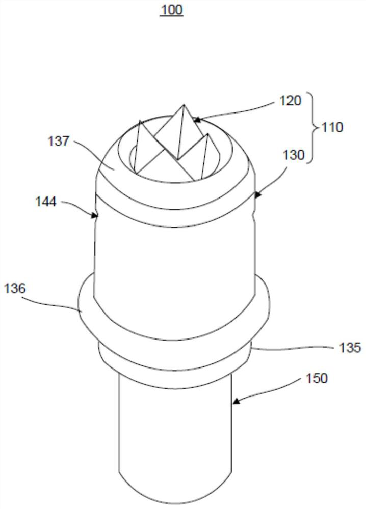
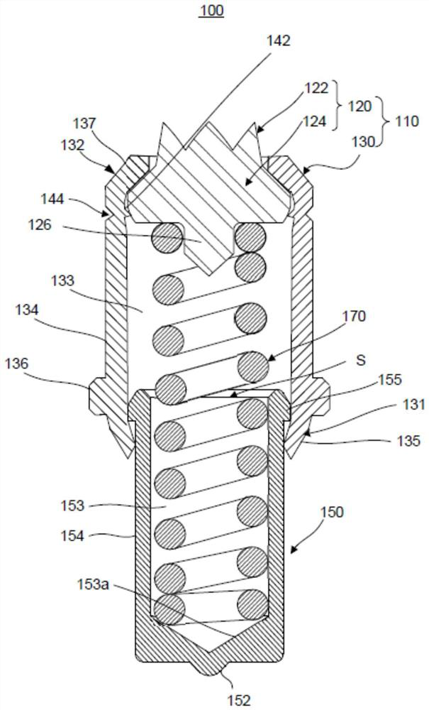
[0075] figure 1 is an external perspective view of the contact pin 100 in the non-use state according to the embodiment of the present invention, figure 2 It is a longitudinal sectional view explaining the structure of the main part of this contact pin.

[0076] figure 1 and figure 2 The illustrated contact pins 100 electrically connect the first electrical component and the second electrical component.

[0077] The contact pin 100 includes a first needle 110 contacting the first electrical c...


PUM


Abstract

A contact pin and a socket are provided. The contact pin includes: a first pin head including a first hollow portion extending from a first contact end portion to a first engagement end portion in an axial direction and opened on a first engagement end portion side; a second pin head including a second hollow portion extending from a second contact end portion to a second engagement end portion in the axial direction and opened on the second engagement end portion side, the second engagement end portion and the first engagement end portion being slidably engaged with each other in a state in which the second hollow portion communicates with the first hollow portion; and a biasing member that is disposed in a space in which the first hollow portion and the second hollow portion communicate with each other, and that biases the first pin head and the second pin head so as to extend in the axial direction. The first pin head comprises a cylindrical main body member that is open on the first engagement end side and the first contact end side; and a contact member which is provided so as to close the open portion of the main body member on the first contact end side, forms the first contact end, and has higher hardness than the main body member and the second pin head.

Description

technical field [0001] The present invention relates to a contact pin and a socket, which are used for electrical connection of electrical components such as IC (Integrated Circuit, integrated circuit) packaging and other electrical component performance tests. Background technique [0002] When inspecting electrical components such as IC packages, sockets equipped with multiple probes are used. The socket is configured to be disposed on an inspection substrate that is a substrate on the inspection device side, and accommodate an IC package that is an inspection object. The socket conducts a test such as a continuity test by electrically connecting the terminals of the accommodated IC package and the terminals of the inspection substrate via the probes as contact pins, and inspects the performance of the IC package. [0003] As a conventional probe, the structure shown in patent document 1 is known, for example. The probe includes: a lower contact member having a hollow sh...

Claims


Application Information

Patent Timeline
Patent Type & Authority Applications(China)
IPC IPC(8): G01R1/067G01R1/073G01R31/28
CPCG01R1/06738G01R1/0675G01R1/07314G01R1/06722G01R31/2886
Inventor 金刺北斗
Owner ENPLAS CORP
Why Eureka
Try Eureka