
A high-barrier photovoltaic backplane automatic cleaning mechanism for new energy development

A photovoltaic backplane and automatic cleaning technology, which is applied in the field of solar energy mining, can solve problems such as affecting the appearance, light blocking, and impact on the service life of the backplane, so as to save manpower and time, improve work efficiency, and simplify cleaning methods.

Active Publication Date: 2021-11-16
SUZHOU YISHENG OPTICAL MATERIAL CO LTD
View PDF8 Cites 0 Cited by
  • Summary
  • Abstract
  • Description
  • Claims
  • Application Information

AI Technical Summary

Problems solved by technology

[0002] As we all know, high-barrier photovoltaic backplane components are important energy mining equipment in the field of solar energy mining. The cells inside can convert solar energy into electrical energy and provide energy for people's life and production. For protection, photovoltaic backplane components are mainly erected in open areas when they are in use. Due to the influence of the natural environment, more dust is easy to deposit on the transparent backplane. The photoelectric conversion efficiency on the back of the photovoltaic cell, and affects the appearance, and has a certain impact on the service life of the backplane; it needs to be cleaned regularly. The existing cleaning method is usually to clean the surface of the photovoltaic backplane directly by workers. However, this kind of The cleaning method is more laborious, requiring more workers, longer working hours, and lower efficiency. At the same time, more impurities are likely to remain on the surface of the photovoltaic backplane, resulting in poor cleaning effect

Method used


Image

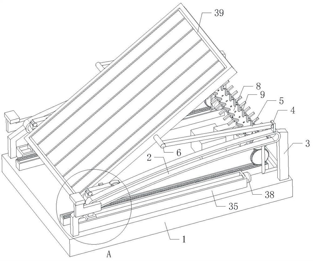
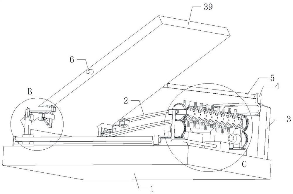
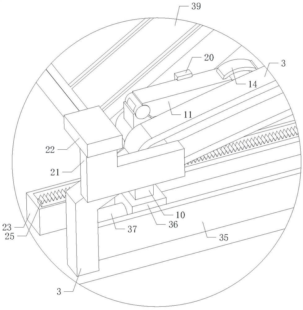
  • A high-barrier photovoltaic backplane automatic cleaning mechanism for new energy development
  • A high-barrier photovoltaic backplane automatic cleaning mechanism for new energy development
  • A high-barrier photovoltaic backplane automatic cleaning mechanism for new energy development

Examples


Embodiment Construction

[0037] The following will clearly and completely describe the technical solutions in the embodiments of the present invention with reference to the accompanying drawings in the embodiments of the present invention. Obviously, the described embodiments are only some, not all, embodiments of the present invention.

[0038] In the description of the present invention, it should be noted that the terms belonging to "center", "upper", "lower", "left", "right", "vertical", "horizontal", "inner", "outer" etc. The indicated orientation or positional relationship is based on the orientation or positional relationship shown in the drawings, and is only for the convenience of describing the present invention and simplifying the description, rather than indicating or implying that the referred device or element must have a specific orientation, or in a specific orientation. construction and operation, therefore, should not be construed as limiting the invention.

[0039]In the description...


PUM


Abstract

The present invention relates to the technical field of solar energy mining, in particular to an automatic cleaning mechanism for a high-barrier photovoltaic backplane for new energy exploitation, including a bottom plate, two arc-shaped guide groove plates are symmetrically arranged on the top of the bottom plate, and the arc-shaped Both ends of the guide groove plate are equipped with vertical plates, and the bottom of the vertical plate is fixed on the bottom plate; the arc guide groove plate is inclined, and the higher end of the arc guide groove plate is installed with the second A mounting plate, the first mounting plate is tilted and rotated to install a support rod, and the outer end of the support rod is installed with a first mounting column; this equipment can realize the automatic cleaning of the photovoltaic backplane body, effectively simplifying the cleaning method, It saves manpower and time and improves work efficiency. At the same time, the impurities on the photovoltaic backplane body fall off downwards, which can effectively avoid the residue of impurities on the surface of the photovoltaic backplane body, improve the cleaning effect and improve the practicability.

Description

technical field [0001] The invention relates to the technical field of solar energy exploitation, in particular to an automatic cleaning mechanism for a high-barrier photovoltaic backplane used in new energy exploitation. Background technique [0002] As we all know, high-barrier photovoltaic backplane components are important energy mining equipment in the field of solar energy mining. The cells inside can convert solar energy into electrical energy and provide energy for people's life and production. For protection, photovoltaic backplane components are mainly erected in open areas when they are in use. Due to the influence of the natural environment, more dust is easy to deposit on the transparent backplane, and the dust is easy to block the light. It affects the photoelectric conversion efficiency of the back of the photovoltaic cell, and affects the appearance, and has a certain impact on the service life of the backplane; it needs to be cleaned regularly. The existing ...

Claims


Application Information

Patent Timeline
Patent Type & Authority Patents(China)
IPC IPC(8): B08B11/04B08B1/00B08B1/04B08B13/00H02S40/10
CPCB08B11/04B08B13/00H02S40/10B08B1/32B08B1/12Y02E10/50
Inventor 居俊杰赵江潘俊
Owner SUZHOU YISHENG OPTICAL MATERIAL CO LTD
Learn More