
An automatic spin welding device

A technology of automatic rotation and welding device, applied in welding equipment, welding accessories, devices for supplying/removing protective gas, etc., can solve the problems of complicated operation, welding deformation, easy generation of air bubbles, etc., to improve the quality of welding seam, control welding The effect of accurate deformation and welding positioning

Active Publication Date: 2021-11-19
LIAONING METAL TECH
View PDF0 Cites 0 Cited by
  • Summary
  • Abstract
  • Description
  • Claims
  • Application Information

AI Technical Summary

Problems solved by technology

[0002] For aerospace titanium alloy storage tank products, the air intake nozzle and filling nozzle are welded with the upper and lower shells. During the welding process, the aerospace titanium alloy storage tank product requires the weld quality level between the air intake nozzle, filling nozzle and the shell High; the current welding equipment is not enough to meet the requirements of the welding grade, and the welding of titanium alloy materials is easy to produce air bubbles, so the welding process has higher requirements for protective gas filling and sealing
[0003] At the same time, the intake nozzles and filling nozzles of this type of aerospace titanium alloy products are mostly special-shaped structural parts, which are difficult to locate relative to the welding position of the shell, and are prone to welding deformation. Traditional manual welding is difficult to meet the demand; moreover, the existing traditional Manual argon arc welding has low reliability of weld seam quality, difficult control of welding positioning size and welding deformation, complicated operation, low efficiency, and poor appearance consistency of weld seam

Method used


Image

  • An automatic spin welding device
  • An automatic spin welding device
  • An automatic spin welding device

Examples


Embodiment Construction

[0022] In order to make the technical problems, technical solutions and beneficial effects solved by the present invention clearer, the present invention will be further described in detail below in conjunction with the accompanying drawings and specific implementation methods. It should be understood that the specific embodiments described here are only used to explain the present invention, and are not intended to limit the present invention.

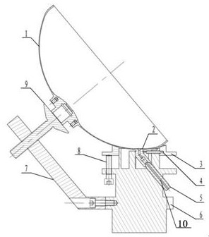
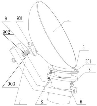
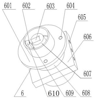
[0023] combined with figure 1 , 2 As shown in and 3, an automatic rotary welding device of the present invention includes an automatic rotary support 6, a positioning device, a sealing device and a support device, and the automatic rotary support 6 is provided with a sealing device and a positioning device; the automatic rotary support 6 A sealing device is provided at the top, a positioning device is provided on one side of the upper part of the automatic rotating support 6 , and a supporting device is provided on the other side of ...


PUM


Abstract

The invention discloses an automatic rotary welding device, which comprises an automatic rotary bracket, a positioning device, a sealing device and a supporting device. The supporting device is set; the upper part of the automatic rotating bracket is provided with a welding cavity, and the nozzle is fixed in the welding cavity, and the positioning device is connected with the nozzle through the welding cavity; the top of the welding cavity is connected with the sealing device, and the shell that is welded with the nozzle is placed on the sealing device The contact position of the housing and the sealing device is sealed and connected by a seal; one end of the supporting device is connected to the lower part of the automatic rotating bracket, and the center of the bottom of the housing is located at the other end of the supporting device. The invention realizes the sealing of the welding cavity, ensures the filling of protective gas and the discharge of redundant air during the welding process, improves the quality of the weld seam, can effectively control the welding deformation, has simple operation, accurate welding positioning and high efficiency.

Description

technical field [0001] The invention belongs to the technical field of welding equipment, and is suitable for welding auxiliary equipment for welding air intake nozzles and filling nozzles of aerospace titanium alloy storage tank products with upper and lower shells, and in particular relates to an automatic rotary welding device. Background technique [0002] For aerospace titanium alloy storage tank products, the air intake nozzle and filling nozzle are welded with the upper and lower shells. During the welding process, the aerospace titanium alloy storage tank product requires the weld quality level between the air intake nozzle, filling nozzle and the shell High; the current welding equipment is not enough to meet the requirements of the welding grade, and the welding of titanium alloy materials is easy to produce bubbles, so the welding process requires high protection gas filling and sealing. [0003] At the same time, the intake nozzles and filling nozzles of such aer...

Claims


Application Information

Patent Timeline
Patent Type & Authority Patents(China)
IPC IPC(8): B23K9/16B23K9/32
CPCB23K9/16B23K9/325
Inventor 董丰园李金平刘阳肇波涛薛昊男李莹莹孙禹孟丽莉王雅虹陈琳
Owner LIAONING METAL TECH
Learn More