
Feed mechanism for chipless cutting machine

A feed mechanism and cutting machine technology, which is applied to metal processing machinery parts, metal processing equipment, feeding devices, etc., can solve the problems of large volume, long stroke of the feed mechanism, and inability to precisely control the feed accuracy of the feed mechanism. , to achieve the effect of compact overall structure, improved feed speed and precise control of feed depth

Pending Publication Date: 2021-10-15
张家港跃邦机械有限公司
View PDF0 Cites 0 Cited by
  • Summary
  • Abstract
  • Description
  • Claims
  • Application Information

AI Technical Summary

Problems solved by technology

[0005] The purpose of the present invention is to provide a feed mechanism for a chipless cutting machine to solve the problem that the stroke of the feed mechanism proposed in the above background technology is long, the volume is large, and the accuracy of the feed mechanism cannot be accurately controlled.

Method used


Image

  • Feed mechanism for chipless cutting machine
  • Feed mechanism for chipless cutting machine
  • Feed mechanism for chipless cutting machine

Examples


Embodiment Construction

[0025] The following will clearly and completely describe the technical solutions in the embodiments of the present invention with reference to the accompanying drawings in the embodiments of the present invention. Obviously, the described embodiments are only some, not all, embodiments of the present invention. Based on the embodiments of the present invention, all other embodiments obtained by persons of ordinary skill in the art without making creative efforts belong to the protection scope of the present invention.

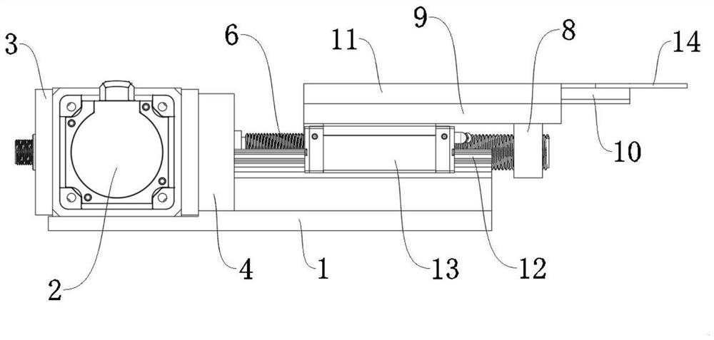
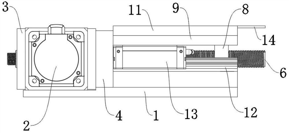
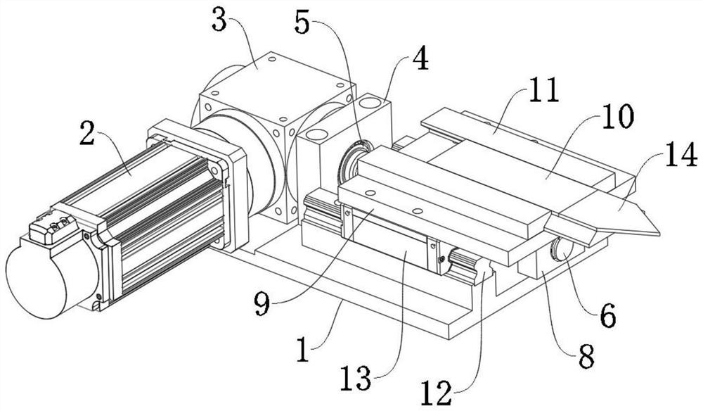
[0026] see Figure 1-7 , an embodiment provided by the present invention is a kind of feed mechanism for a chipless cutting machine, including a knife holder 1, a servo motor 2, a precision steering gear 3, a bearing seat 4, a bearing 5, a ball-type linear guide 12, a ball-type linear guide Slide rail 13 and cutting knife 14, bearing seat 4 is fixed on the outer surface of knife rest 1, feed screw rod 6 is connected with bearing seat 4 through bearing 5, and t...


PUM


Abstract

The invention relates to the technical field of cutting machine production, in particular to a feed mechanism for a chipless cutting machine. The feed mechanism comprises a knife holder, a servo motor, a precision steering gear, a bearing seat, a bearing, a ball-type linear guide rail, a ball-type linear slide rail and a cutting knife, wherein the servo motor and a feed screw are arranged at 90 degrees, the outer surface of the feed screw is provided with two sections of threads in the same direction, the two sections of threads are adjacent, the length of the thread at one side away from the precision steering gear is twice that of the thread at one side close to the precision steering gear, the diameter of the thread at the side close to the precision steering gear is greater than that of the thread at the side away from the precision steering gear, and the pitch of the thread at the side away from the precision steering gear is twice that at the side close to the precision steering gear; and a second sliding block sleeves one side, away from a first sliding block, of the outer surface of the feed screw. By changing the driving mode, accurate control is facilitated, and the driving stroke of the feed mechanism is shortened while the feed depth is not changed.

Description

technical field [0001] The invention relates to the technical field of cutting machine production, in particular to a knife feed mechanism for a chipless cutting machine. Background technique [0002] The chipless cutting machine is a kind of cutting machine, which is characterized by low cutting noise and numerical control operation. The feed mechanism is the core component of the chipless cutting machine, which is used to control the depth of the feed to achieve precise cutting. [0003] Existing chipless cutting machines generally use oil cylinders or the cooperation of cylinders and slide rails and sliders as the feeding mechanism, but this design has the following disadvantages: 1. The stroke of the feeding mechanism is long, but the internal space of the equipment is limited, so it can only be passed through Increase the volume of the overall equipment to adapt to the installation of the feeding mechanism, which will result in a larger equipment footprint and higher pr...

Claims


Application Information

Patent Timeline
Patent Type & Authority Applications(China)
IPC IPC(8): B23Q5/36B23Q5/40
CPCB23Q5/36B23Q5/40
Inventor 马军
Owner 张家港跃邦机械有限公司
Learn More