Method for grabbing specified part of shaft workpiece for feeding

A technology for shaft workpieces and parts, which is applied in the field of automatic feeding, can solve problems such as inaccurate axis angles, and achieve the effects of less positional constraints, less grabbing and touching, and high flexibility

Active Publication Date: 2021-10-15
TIANJIN UNIV
View PDF6 Cites 1 Cited by
  • Summary
  • Abstract
  • Description
  • Claims
  • Application Information

AI Technical Summary

Problems solved by technology

In fact, due to the tilt of the light source, there are black shadows or reflections on the edge of the axis outline, which will cause the axis angle obtained by this method to be inaccurate

Method used


Image

  • Method for grabbing specified part of shaft workpiece for feeding
  • Method for grabbing specified part of shaft workpiece for feeding
  • Method for grabbing specified part of shaft workpiece for feeding

Examples


Embodiment Construction

[0031] The present invention will be described in detail below in conjunction with the accompanying drawings and specific embodiments.

[0032] As shown in the accompanying drawings, a method for grabbing a specified part of a shaft workpiece according to the present invention for loading includes the following steps:

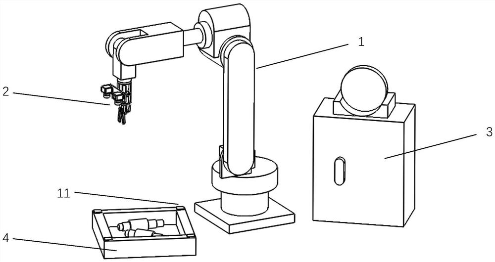
[0033] Step 1. Connect the device and paste a rectangular sticker 11 of a specific color on the four corners of the top frame of the open material box 4;

[0034] The open material box 4 is a rectangular body without a top, and several non-overlapping shaft parts are laid flat in the material box. The area where the shaft workpiece is located is the rectangular area that accommodates shaft parts in the material box 4 , that is, the rectangular area after the frame is removed from the open material box 4 .

[0035] The process of connecting the equipment is as follows: install the end effector 2 on the end of the mechanical arm 1, and connect the control line o...


PUM


Abstract

The invention discloses a method for grabbing a specified part of a shaft workpiece for feeding. The method comprises the following steps of identifying rectangular stickers with specific colors at four corners of a material box to obtain three-dimensional coordinates of the center of the material box and an area where the shaft workpiece is located; selecting a workpiece contour from the area for rough drawing, and obtaining the mass center and the axis of the workpiece according to the outer edge of a rough contour; rotating a left image shot by a camera to enable the axis of the workpiece in the left image to be horizontal, obtaining the minimum enclosing rectangle of the workpiece at the moment, and establishing a relation between the minimum enclosing rectangle and a pre-stored template image, so as to obtain three-dimensional coordinates of corresponding points of the workpiece in the left image according to a to-be-clamped point and a chuck clamping point marked in the template image; and clamping the to-be-clamped point of the workpiece by an end effector on a mechanical arm, sending the workpiece to a machine tool chuck, and clamping the workpiece at the chuck clamping point. The method can specify a clamping part, and is suitable for various shaft workpieces, and high in practicability.

Description

technical field [0001] The invention relates to an automatic feeding method, in particular to a method of using machine vision for positioning and using a six-degree-of-freedom series mechanical arm to grab shaft parts for feeding. Background technique [0002] In the field of automatic loading and unloading, it is often necessary to design complex mechanisms to ensure the trajectory and precise position of the movement. These devices are often only suitable for a small class or several similar workpieces, lacking versatility. On the other hand, with the development of multi-degree-of-freedom manipulators, the positioning accuracy and repeatability of the manipulators have been greatly improved. Cameras are often used as sensors when calculating the position of workpieces. Through a suitable algorithm, the camera can obtain the pose of the workpiece, and the accuracy can meet the needs of most loading and unloading. [0003] Shaft parts are a large category of workpieces ...

Claims


Application Information

Patent Timeline
Patent Type & Authority Applications(China)
IPC IPC(8): B25J9/16B23Q7/04
CPCB25J9/1664B25J9/1697B23Q7/04
Inventor 韩雪松余江宁
Owner TIANJIN UNIV
Why Eureka
Try Eureka