Clamping device and method for controlling clamping force on workpiece through linear motor

A linear motor and clamping device technology, applied in the direction of manufacturing tools, chucks, manipulators, etc., can solve problems such as inaccurate clamping force, complex structure, and easy damage to the motor, and achieve high-precision motion control and high-response motion control , the effect of precise clamping force

Pending Publication Date: 2021-10-15
HUAIYIN INSTITUTE OF TECHNOLOGY
View PDF5 Cites 2 Cited by
  • Summary
  • Abstract
  • Description
  • Claims
  • Application Information

AI Technical Summary

Problems solved by technology

[0004] The widely used driving method of mechanical claws is to drive the worm and gears to rotate by a rotating motor to open and close the mechanical claws, and the structure is complex.
However, due to the small operating speed of the small rotating motor, the opening and closing response of the mechanical claw is slow
It is difficult to control the clamping force of the mechanical claw during use, resulting in inaccurate clamping force
And when the mechanical claw clamps the workpiece and cannot move, the rotating motor continues to run idling, and the motor is easily damaged due to overload, which affects the efficiency and reliability of the mechanical claw

Method used


Image

  • Clamping device and method for controlling clamping force on workpiece through linear motor
  • Clamping device and method for controlling clamping force on workpiece through linear motor
  • Clamping device and method for controlling clamping force on workpiece through linear motor

Examples


Embodiment

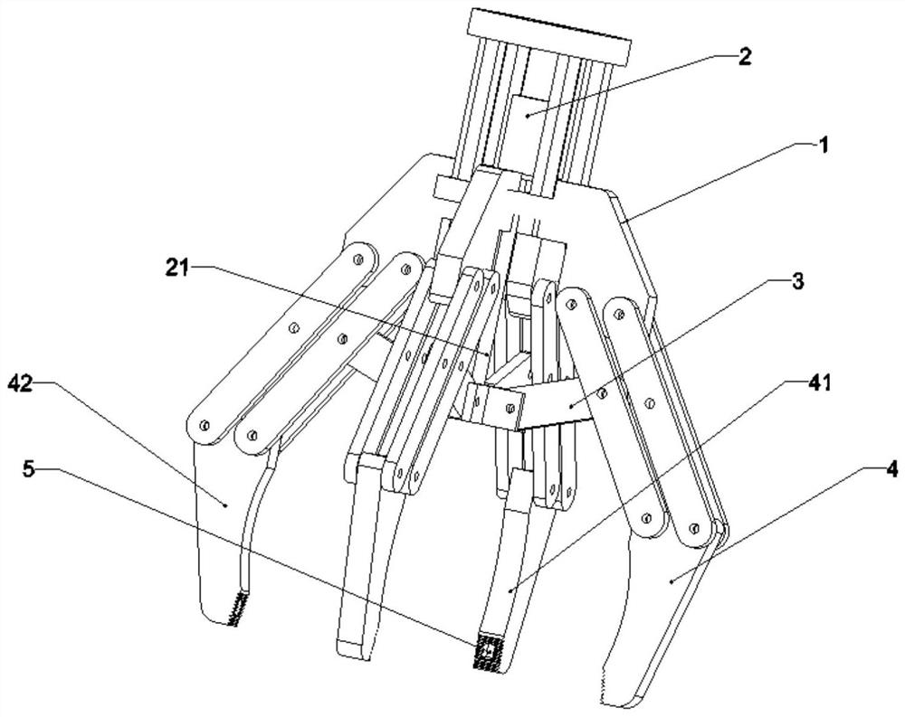
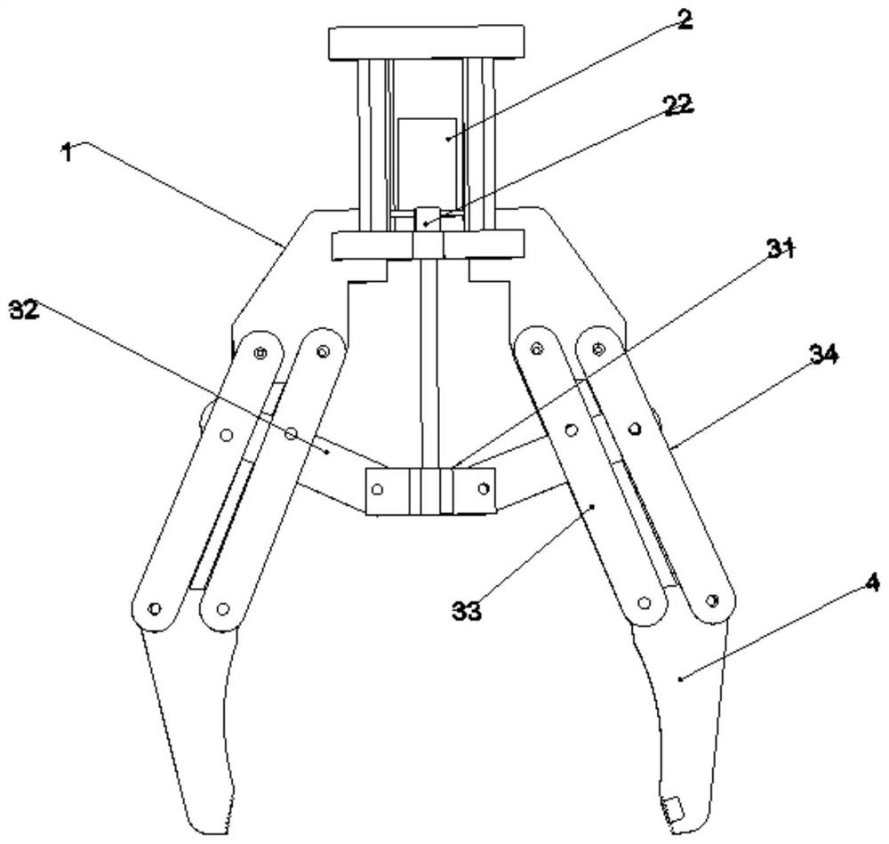
[0029] like figure 1 and figure 2 As shown, in the embodiment of the present invention, the clamping device that controls the magnitude of the clamping force on the workpiece by a linear motor includes a base 1 , a linear motor 2 , a telescopic rod 21 , a transmission mechanism 3 and a clamping claw mechanism 4 . The clamping device sends an electric signal through the control unit CPU to drive the telescopic rod 21 to move, and then drives the transmission mechanism 3 to control the opening and closing of the clamping claw mechanism 4 .

[0030] The bottom surface of the base 1 is used to fix the linear motor 2 and the transmission mechanism 3, and the matching bolt holes on the top surface of the base 1 are connected with the required mechanical arm, AGV trolley and other chassis units, and a cylindrical protection is arranged around the base 1. Cover to prevent dust and debris from entering the motor components and causing the clamping device to work abnormally.

[0031]...


PUM


Abstract

The invention discloses a clamping device and method for controlling the clamping force on a workpiece through a linear motor. The clamping device comprises a base, the linear motor, a telescopic rod, a control unit, a transmission mechanism and a clamping jaw mechanism; the clamping jaw mechanism comprises friction force sensing jaws and mechanical clamping jaws, and friction force sensors are arranged on the contact faces of the friction force sensing jaws and the workpiece; the linear motor is connected with the telescopic rod; and the control unit sends an electric signal, the linear motor drives the telescopic rod to move, and then the transmission mechanism is driven to control opening and closing of the clamping jaw mechanism. According to the clamping device, the friction force sensing jaws are in contact with the workpiece, so that the friction force sensors sense vertical friction force generated when the workpiece is in contact with the friction force sensing jaws; and the friction force sensors process and judge the vertical friction force and feeds back the vertical friction force to a CPU, the CPU controls a driving signal of the linear motor and enables the clamping device to provide clamping force according to the friction force generated by relative sliding between the contact faces of the mechanical clamping jaws and the workpiece, and accurate control over the clamping force is achieved.

Description

technical field [0001] The invention relates to a mechanical clamping device, in particular to a clamping device and a method for controlling the clamping force of a workpiece by a linear motor. Background technique [0002] A mechanical claw is a mechanical component that can achieve functions similar to a human hand. The mechanical claw is an automatic device with the function of grabbing and moving workpieces used in the automated production process. It is a new type of device developed in the mechanized and automated production process. [0003] At present, mechanical claws are more and more widely used. In the machinery production industry, it can be used for component assembly, handling, loading and unloading of processed workpieces, and thus saves huge workpiece transportation devices. It has a compact structure and strong adaptability. [0004] The widely used driving method of mechanical claw is to drive the worm and gear to rotate by the rotating motor to open and...

Claims


Application Information

Patent Timeline
Patent Type & Authority Applications(China)
IPC IPC(8): B25J15/02B25J15/10
CPCB25J15/0206B25J15/10
Inventor 朱建辉葛霄薛蒙蒙管志洋冒纪凯武继权何宇杰冯壮戴建国王程
Owner HUAIYIN INSTITUTE OF TECHNOLOGY
Why Eureka
Try Eureka