A multifunctional vibration contact testing machine

A contact test, multi-functional technology, used in vibration testing, machine/structural component testing, measuring devices, etc., to solve problems such as micro-cracks in the contact area, large space occupied by weights, and errors

Active Publication Date: 2020-01-31
SOUTHWEST JIAOTONG UNIV +1
View PDF13 Cites 0 Cited by
  • Summary
  • Abstract
  • Description
  • Claims
  • Application Information

AI Technical Summary

Problems solved by technology

The contact system is often served under multiple coupling conditions such as impact and cyclic dynamic load. Vibration and stress waves will cause fretting and wear of the contact interface, and micro-cracks, peeling and wear will occur in the contact area, which will intensify the vibration. , temperature rise, noise increase, etc., its tribological behavior is quite complicated
[0003] Such as patent 1 (application number is CN104019989A) discloses a kind of lever electric loading type rolling contact fatigue testing machine, adopts the loading method that lever, weight, servo motor and ball screw combine, although can realize continuous large-scale loading, but The weight takes up a lot of space, which will cause a large error when rotating at high speed, the load change is limited, and the test object is relatively single
Another example is the high-speed rolling contact fatigue wear test bench disclosed in Patent 2 (the application number is CN108426795A), which uses a hydraulic cylinder to load the test piece, which can realize continuous loading up to 3kN, but the hydraulic loading is easy to cause environmental pollution, and the introduction of the hydraulic system is relatively complicated.
The above-mentioned testing machines can only carry out contact behavior research under static load conditions, and cannot perform tribological tests coupled with rotation and dynamic loads, and the contact form is relatively simple; thereby affecting its service life

Method used


Image

  • A multifunctional vibration contact testing machine
  • A multifunctional vibration contact testing machine
  • A multifunctional vibration contact testing machine

Examples


no. 1 example

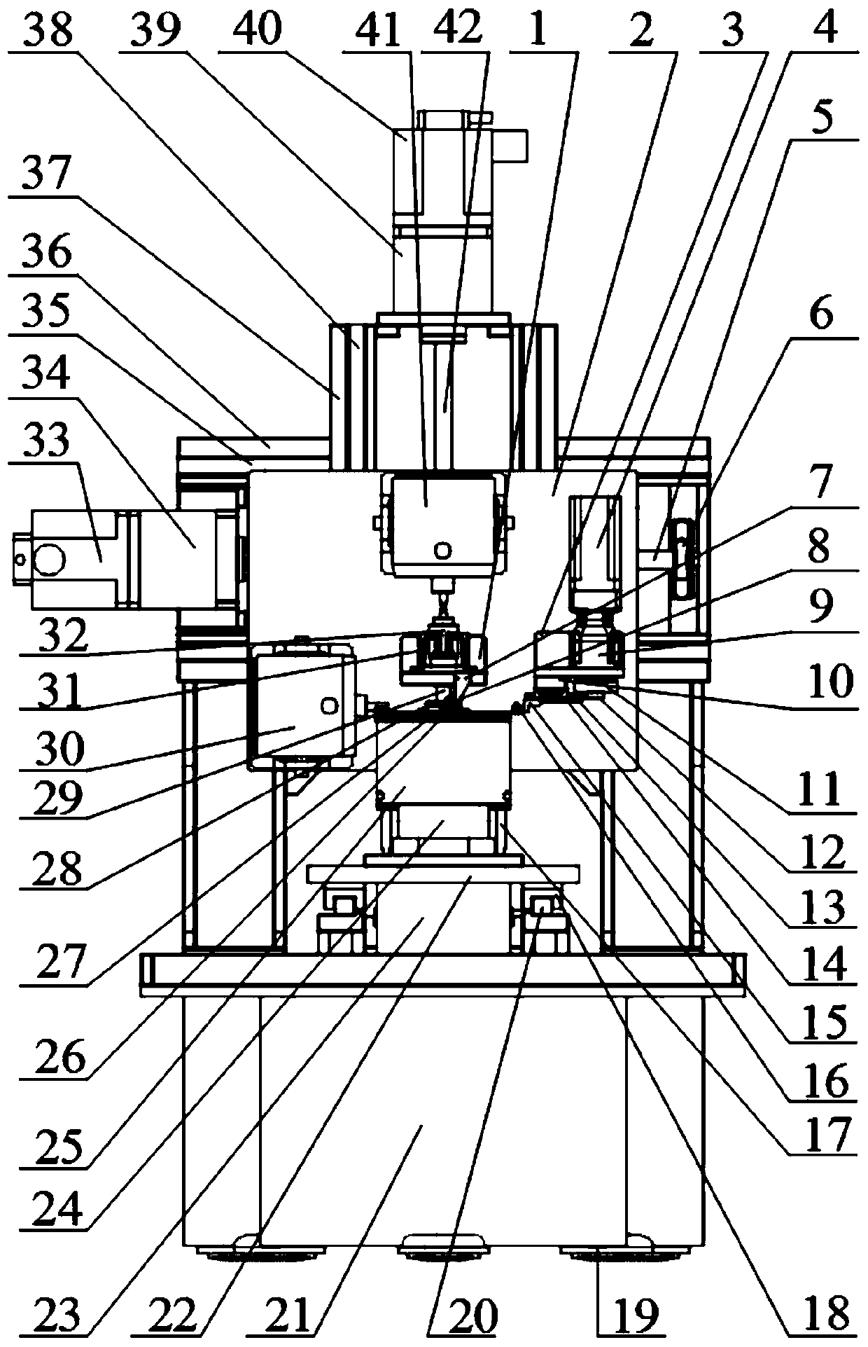
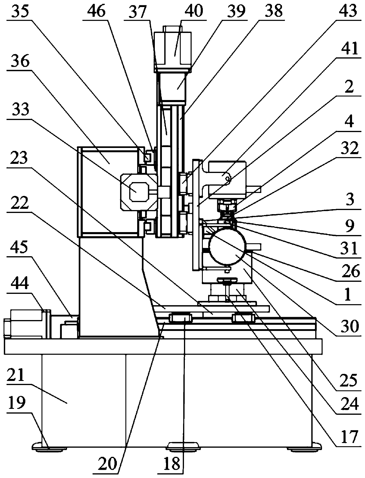
[0042] Please refer to figure 1 and figure 2 , a multifunctional vibration contact testing machine provided by the present invention, the testing machine includes a body, a transmission system, a rotating system, a test piece installation and lubrication system, an exciting load system, a measurement and acquisition system, and a display and control system, wherein: The body includes a platform frame 21, a standing frame 36 and an adjustment foot pad 19; the transmission system includes the first linear guide rail 20, the first linear guide rail slider 18, the first lead screw, the first lead screw holder, The first servo motor mounting base 45, the first servo motor 44, the first coupling, the second linear guide rail 35, the second linear guide rail slider 46, the second trapezoidal screw 5, the second trapezoidal screw fixing seat 6, The second servo motor 33, the second servo motor mount 34, the second coupling, the lateral movement bracket 37, the third linear guide rai...


PUM


Abstract

The invention discloses a multifunctional vibration contact testing machine, which includes a frame, a transmission system, a rotating system, a test piece installation and lubrication system, an excitation load system, a measurement and acquisition system, and a display and control system; the frame includes a platform machine frame and standing frame; the transmission system provides a certain movable range for the upper and lower test piece mounting tables; the rotation system provides high-speed rotation motion for the lower test piece; the test piece installation and lubrication system provides a mounting platform and lubricating medium for the test piece; The load system provides lateral / vertical / two-way vibration excitation / vertical independent load for the upper and lower test pieces; the measurement and acquisition system detects and analyzes the parameters required for the test; the display and control system displays the changes of the test parameters in real time and controls the testing machine; the present invention The testing machine provided can complete the research on dynamic tribological characteristics of test pieces with various contact forms under a wide range of variable load, variable frequency, variable speed, dry state and lubrication and other multi-working conditions.

Description

technical field [0001] The invention relates to the technical field of dynamic contact testing devices, in particular to a multifunctional vibration contact testing machine. Background technique [0002] There are many contact pairs in mechanical equipment parts, wheel-rail systems, pantograph-network systems, such as machine tool guide rails, gear meshing, wheel-rail contact, pantograph-network contact, bearing contact, etc., which are widely used in aerospace, high-speed railways, automobiles, machinery The rapid development of high-tech fields such as equipment has put forward higher requirements for the service performance of parts and components. The contact system is often served under multiple coupling conditions such as impact and cyclic dynamic load. Vibration and stress waves will cause fretting and wear of the contact interface, and micro-cracks, peeling and wear will occur in the contact area, which will intensify the vibration. , temperature rise, noise increas...

Claims


Application Information

Patent Timeline
Patent Type & Authority Patents(China)
IPC IPC(8): G01M7/06G01M7/02
Inventor 张允王茜任超王强王战江
Owner SOUTHWEST JIAOTONG UNIV
Why Eureka
Try Eureka