Agricultural ventilator wind collector and design method thereof

A design method and technology for air collectors, which are applied in agricultural machinery, mechanical equipment, machines/engines, etc., can solve problems such as use by ordinary technicians, improve ventilation energy efficiency ratio, improve internal flow pattern, and increase gain Effect

Active Publication Date: 2021-10-15
CHINA AGRI UNIV
View PDF5 Cites 0 Cited by
  • Summary
  • Abstract
  • Description
  • Claims
  • Application Information

AI Technical Summary

Problems solved by technology

[0004] Up to now, the design of the structural parameters of the wind collector for agricultural fans mostly relies on experience, and there are no ready-made achievements for those of ordinary skill in the art to use. Based on the above-mentioned background, the present invention is proposed

Method used


Image

  • Agricultural ventilator wind collector and design method thereof
  • Agricultural ventilator wind collector and design method thereof
  • Agricultural ventilator wind collector and design method thereof

Examples


Embodiment 1

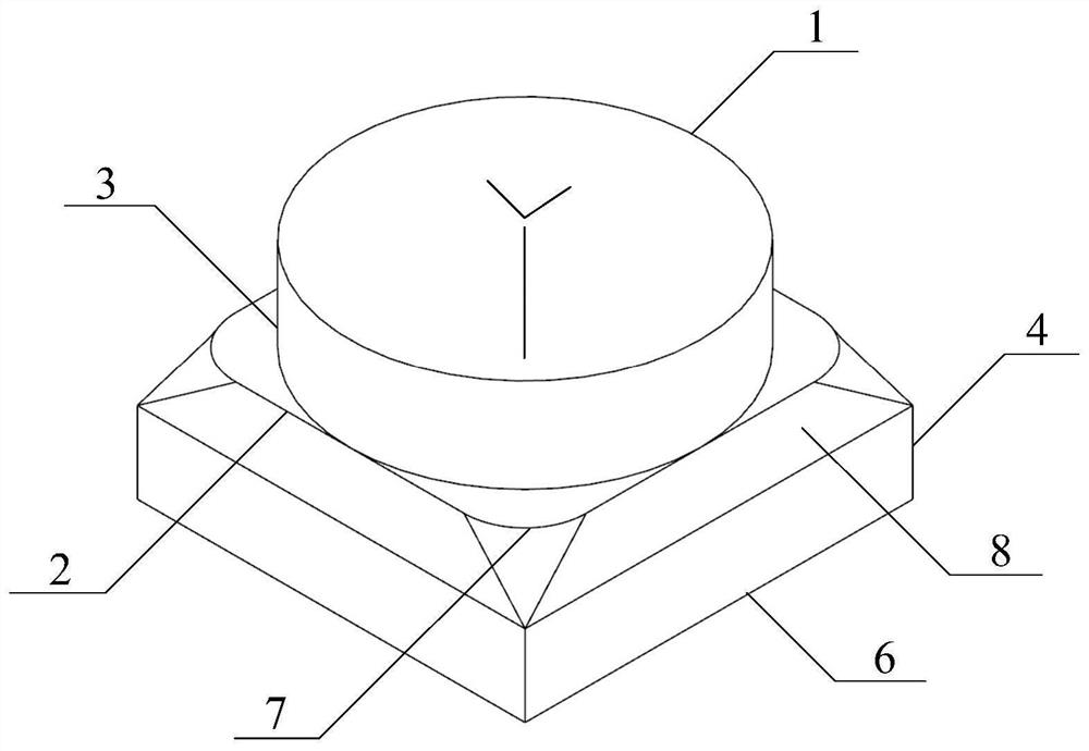
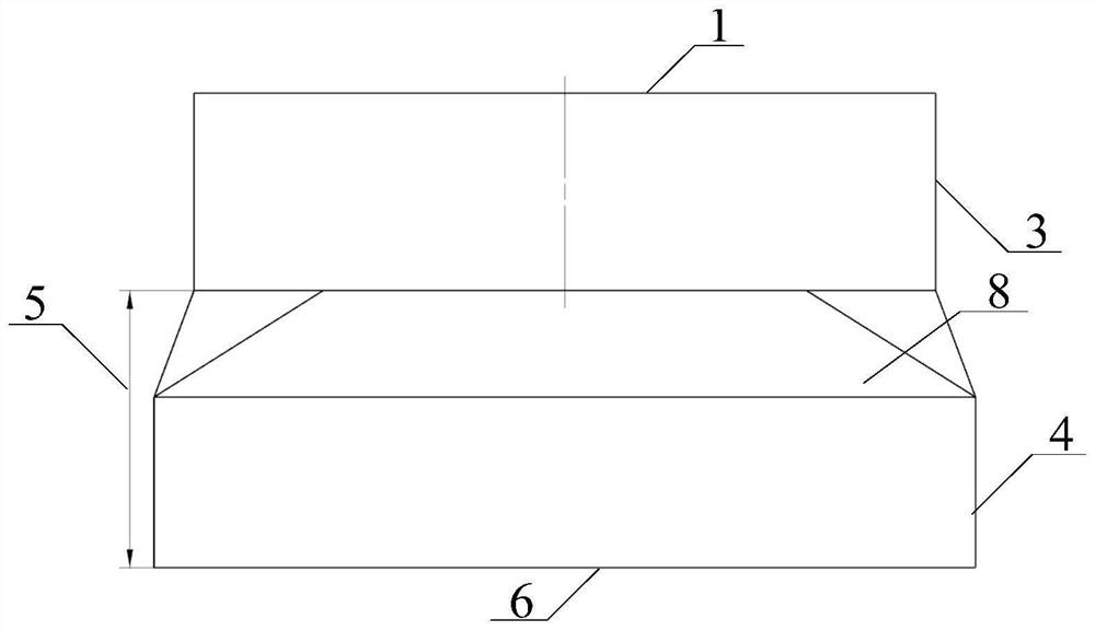
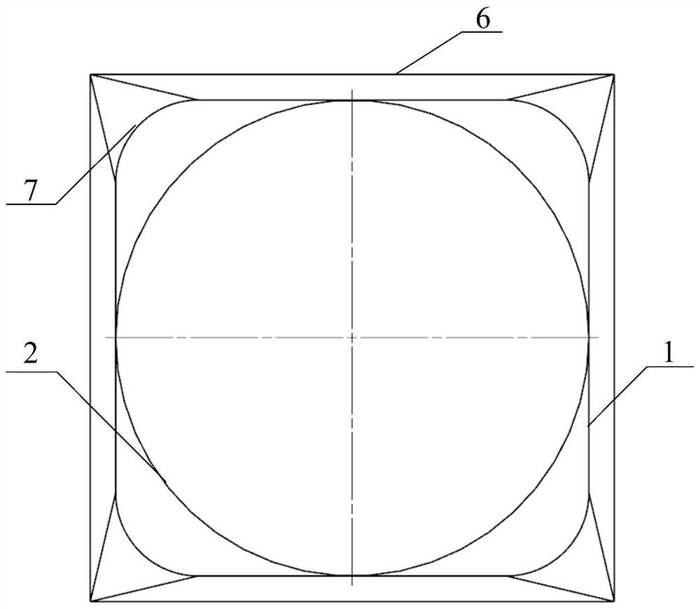
[0090] A 24-inch agricultural fan air collector structure such as Figure 1a , Figure 1b with Figure 1c Shown (the 24-inch agricultural ventilator is hereinafter referred to as the prototype). The speed of the fan is 825r / min, the diameter of the air collector outlet 1 is 683mm, the length of the inlet straight section 4 is 130mm, the length of the inlet side 6 is 762mm, and the radius of the air collector fillet 7 is 100mm.

[0091] Under design conditions, the prototype has a ventilation volume of 9352.698m3 / h and a ventilation energy efficiency ratio of 18.76m 3 / (h·W).

[0092] In order to improve the above-mentioned 24-inch agricultural fan collector, the following steps are taken:

[0093] S1. Measure the diameter of the air collector outlet 1 of the 24-inch agricultural fan air collector X3

[0094] After measurement, the diameter X3 of the air collector outlet 1 is 683 mm.

[0095] S2. Determine the weight of ventilation volume and ventilation energy efficiency ...

Embodiment 2

[0120] A 24-inch agricultural axial flow fan adopts the following steps:

[0121] S1. Measure the diameter of the air collector outlet 1 of the 24-inch agricultural fan air collector X3

[0122] After measurement, the diameter X3 of the air collector outlet 1 is 685mm.

[0123] S2. Determine the weight of ventilation volume and ventilation energy efficiency ratio

[0124] Set the weight of ventilation volume and ventilation energy efficiency ratio to 5:6.

[0125] S3. Determine the target ventilation volume or target ventilation energy efficiency ratio

[0126] Determine the ventilation volume of the air collector of the agricultural ventilator as 9353.116×125%=11691.395m 3 / h, ventilation energy efficiency ratio is 19.01×125%=23.76m 3 / (h·W).

[0127] S4. Solve the structural parameters of the air collector

[0128] For the air collector of a 24-inch agricultural fan, the function model of the ventilation volume, ventilation energy efficiency ratio and the structural pa...


PUM

PropertyMeasurementUnit
Diameteraaaaaaaaaa
Lengthaaaaaaaaaa
Lengthaaaaaaaaaa

Abstract

The invention belongs to the field of mechanical application equipment, and particularly relates to an agricultural ventilator wind collector and a design method thereof. The design method comprises the following steps that S1, the diameter X3 of a wind collector outlet (1) of the agricultural ventilator wind collector is measured; S2, the ventilation quantity and the ventilation energy efficiency ratio weight are determined; S3, a target ventilation quantity or a target ventilation energy efficiency ratio is determined; S4, structural parameters of the wind collector are solved; and S5, according to the structural parameters, obtained in the step S4, of the wind collector, the 24-inch agricultural ventilator wind collector is constructed. According to the agricultural ventilator wind collector, the ventilation quantity and the ventilation energy efficiency ratio of an agricultural ventilator are remarkably improved through a function model of the ventilation quantity, the ventilation energy efficiency ratio and the structural parameters of the wind collector. According to the agricultural ventilator wind collector, the ventilation energy efficiency ratio of the agricultural ventilator can be increased by 1.3%-7%, and the ventilation quantity can be increased by 2.7%-6%.

Description

technical field [0001] The invention belongs to the field of mechanical application equipment, and in particular relates to an air collector for an agricultural fan and a design method thereof. Background technique [0002] As a kind of impeller machinery for sucking, transporting and increasing gas energy, agricultural ventilator has been widely used with the rapid development of modern livestock and poultry breeding industry and greenhouse facility agriculture. [0003] As an important air intake part of the agricultural fan, the air collector is connected to the diffuser (diffuser) along the direction of the airflow, and is connected with the louvers, motor rotors, blades, etc. inside, and plays a role in gradually accelerating the airflow in it. Next, the effect of a uniform intake velocity field is obtained. The air collector has a great influence on the performance of the fan. According to the introduction of "Practical Technology of Axial Flow Fan" (edited by Chang Z...

Claims


Application Information

Patent Timeline
IPC IPC(8): F04D29/00F04D25/08G06F30/17
CPCF04D29/002F04D25/08G06F30/17Y02P60/14
Inventor 丁涛李松刘志伟王朝元施正香
Owner CHINA AGRI UNIV
Why Eureka
Try Eureka