Cutter detection device

A detection device and tool technology, applied in the direction of measuring device, mechanical measuring device, auxiliary device, etc., can solve the problems of scrapped workpiece, reduced service life of alloy materials, low degree of automation, etc., to achieve good cleaning, improve stability, and improve work efficiency The effect of efficiency

Active Publication Date: 2021-10-15
YANTAI FRIED ROBOT CO LTD
View PDF15 Cites 2 Cited by
  • Summary
  • Abstract
  • Description
  • Claims
  • Application Information

AI Technical Summary

Problems solved by technology

[0002] In the process of metal parts processing, the tool and its fixing frame are usually installed on the machine tool for processing and production. Usually, the lathe uses the tool to turn the workpiece. After continuous work, the alloy material at the end of the tool wears a lot, and it needs to be regularly The testing staff infers the replacement time based on the length of use and wear conditions. At the same time, if the flatness of the alloy part at the end of the tool is not flat enough, the alloy installed during the processing is easy to shake, which will lead to the service life of the alloy material. reduce, and cause insufficient turning precision of the workpiece, and even directly lead to the scrapping of the workpiece, which is time-consuming and laborious. Therefore, in the production process of the tool, the produced tool needs to detect the flatness of the alloy part installed at the end of the tool, so as to prevent it from being used during use. It will cause greater losses. At the same time, the tools will be contaminated with dust during the production and transfer process. If it is not cleaned in time, it will affect the accuracy of the detection. Due to the large number of tools in the production process, the degree of automation is low, and the manual detection efficiency is low.

Method used


Image

  • Cutter detection device
  • Cutter detection device
  • Cutter detection device

Examples


Embodiment Construction

[0029] The following will clearly and completely describe the technical solutions in the embodiments of the present invention with reference to the accompanying drawings in the embodiments of the present invention. Obviously, the described embodiments are only some, not all, embodiments of the present invention. Based on the embodiments of the present invention, all other embodiments obtained by persons of ordinary skill in the art without creative efforts fall within the protection scope of the present invention.

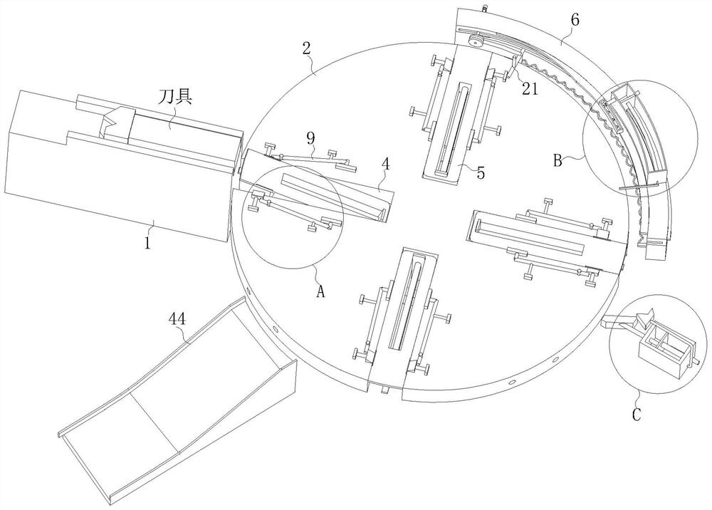
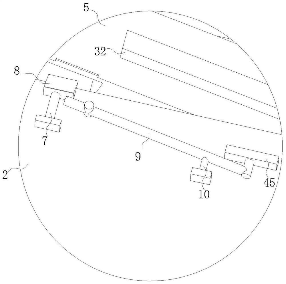
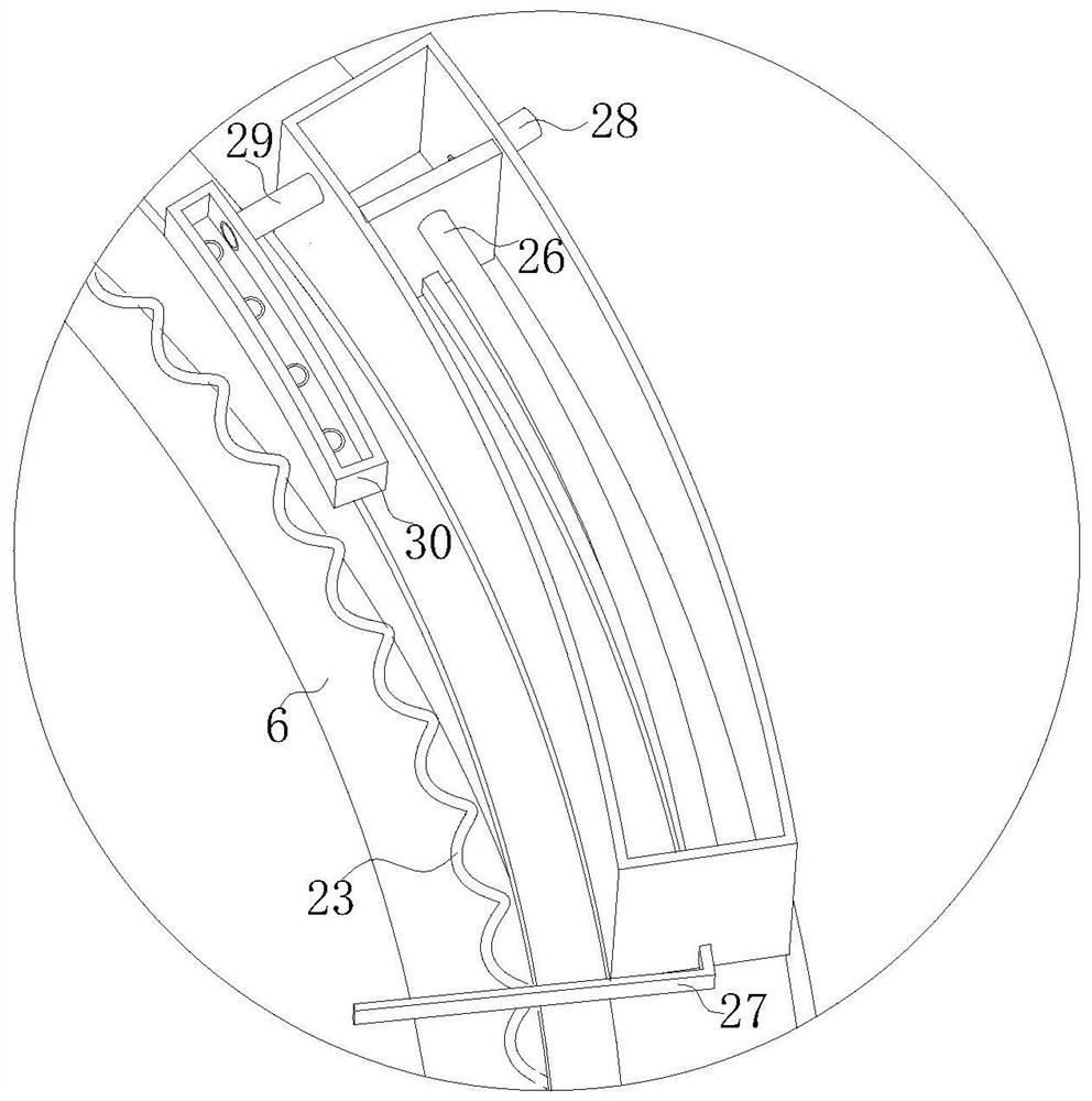
[0030] see Figure 1-11, the present invention provides a technical solution: a tool detection device, including a feeding mechanism 1 for tool delivery, characterized in that a turntable 2 is provided on the right side of the feeding mechanism 1, and a turntable 2 is provided at the lower end of the turntable 2 Motor 3, described turntable 2 is divided into clamping section 201, cleaning section 202, detection section 203, unloading section 204, and described turn...


PUM


Abstract

The invention discloses a cutter detection device in the technical field of cutter detection devices. The cutter detection device comprises a feeding mechanism, a turntable is arranged on the right side of the feeding mechanism, a motor is arranged at the lower end of the turntable, a plurality of notches are uniformly formed in the turntable at equal angles, a baffle is rotatably arranged in each notch, and a pushing mechanism is arranged in each baffle. Clamping mechanisms are symmetrically arranged on the two sides of the upper end of each notch, an arc-shaped plate is arranged at the rear side end of the turntable, a cleaning mechanism is slidably arranged in the arc-shaped plate, an air blowing mechanism is arranged on the upper end face of the arc-shaped plate, a detection mechanism is arranged at the right side end of the turntable, and a discharging mechanism is arranged at the front end of the turntable; through the arrangement, the problems that when the flatness of the cutter is detected, the cutter is contaminated by dust and the like in the production and transfer process, the detection accuracy is affected if the cutter cannot be cleaned, and the number of cutters is large in the production process, the automation degree is low, and the manual detection efficiency is low can be solved.

Description

technical field [0001] The invention relates to the technical field of tool detection devices, in particular to a tool detection device. Background technique [0002] In the process of metal parts processing, the tool and its fixing frame are usually installed on the machine tool for processing and production. Usually, the lathe uses the tool to turn the workpiece. After continuous work, the alloy material at the end of the tool wears a lot, and it needs to be regularly The testing staff infers the replacement time based on the length of use and wear conditions. At the same time, if the flatness of the alloy part at the end of the tool is not flat enough, the alloy installed during the processing is easy to shake, which will lead to the service life of the alloy material. reduce, and cause insufficient turning precision of the workpiece, and even directly lead to the scrapping of the workpiece, which is time-consuming and laborious. Therefore, in the production process of th...

Claims


Application Information

Patent Timeline
Patent Type & Authority Applications(China)
IPC IPC(8): G01B5/28G01B5/00B23B25/06B23Q17/09B23Q11/00
CPCG01B5/28G01B5/0002B23B25/06B23Q17/0904B23Q11/0042
Inventor 苏峰王虹孙欣
Owner YANTAI FRIED ROBOT CO LTD
Why Eureka
Try Eureka