
Stamping die with rotary waste cutter and stamping method thereof

A technology of stamping dies and waste knives, which is applied in the field of stamping parts processing, can solve the problems of the influence of the trimming section quality of workpieces, the complex structure of upper die trimming knife blocks, cumbersome and time-consuming disassembly work, etc., so as to improve work efficiency and facilitate The post-maintenance and disassembly process is simple and fast

Inactive Publication Date: 2021-10-19
东莞市海洛实业有限公司
View PDF8 Cites 0 Cited by
  • Summary
  • Abstract
  • Description
  • Claims
  • Application Information

AI Technical Summary

Problems solved by technology

Moreover, around the cut-off point, it has a certain impact on the quality of the trimmed section of the workpiece.
It will cause defects such as burrs and other defects on the effective surface of the stamped workpiece corresponding to the position of the scrap cutter, which will seriously affect the surface quality of the workpiece
[0004] The edge trimmer block of the upper die is a consumable part, which needs to be disassembled and maintained or replaced frequently. However, in the existing stamping die, the edge trimmer block of the upper die has a complicated structure, and the disassembly and assembly work is cumbersome and time-consuming. caused great inconvenience

Method used


Image

  • Stamping die with rotary waste cutter and stamping method thereof
  • Stamping die with rotary waste cutter and stamping method thereof
  • Stamping die with rotary waste cutter and stamping method thereof

Examples


Embodiment Construction

[0043] In order to make the purpose, technical solutions and advantages of the embodiments of the present invention more clear, the technical solutions in the embodiments of the present invention will be clearly and completely described below in conjunction with the accompanying drawings in the embodiments of the present invention. Obviously, the described embodiments It is a part of embodiments of the present invention, but not all embodiments. Based on the embodiments of the present invention, all other embodiments obtained by persons of ordinary skill in the art without making creative efforts belong to the protection scope of the present invention.

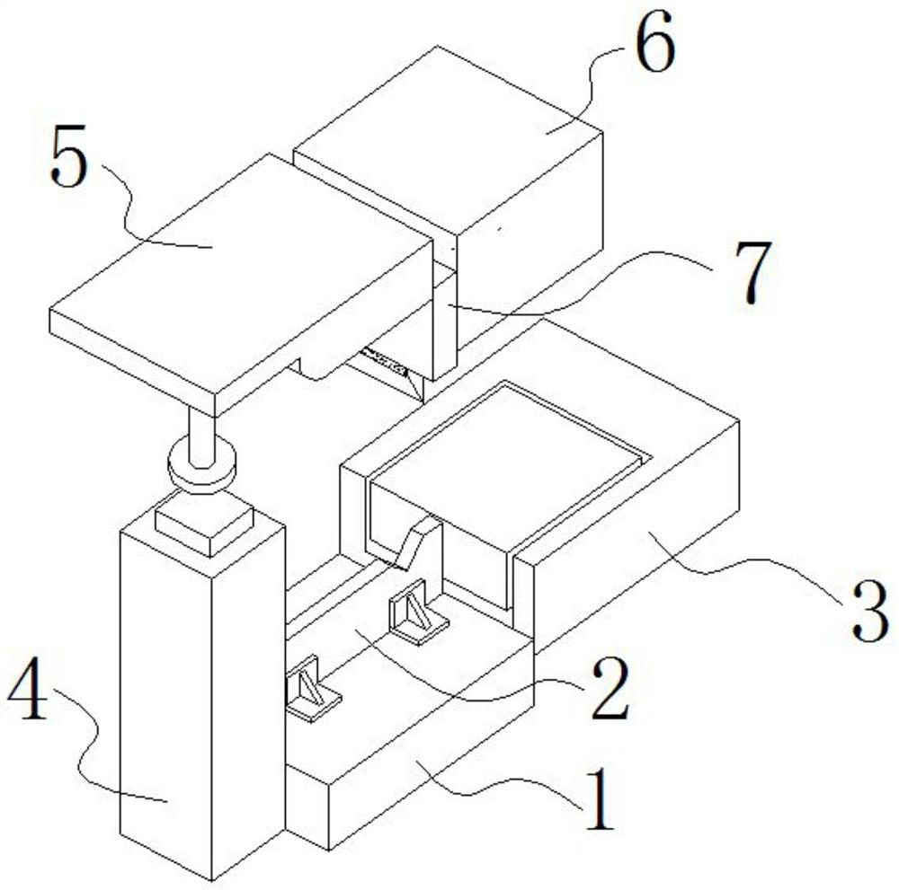
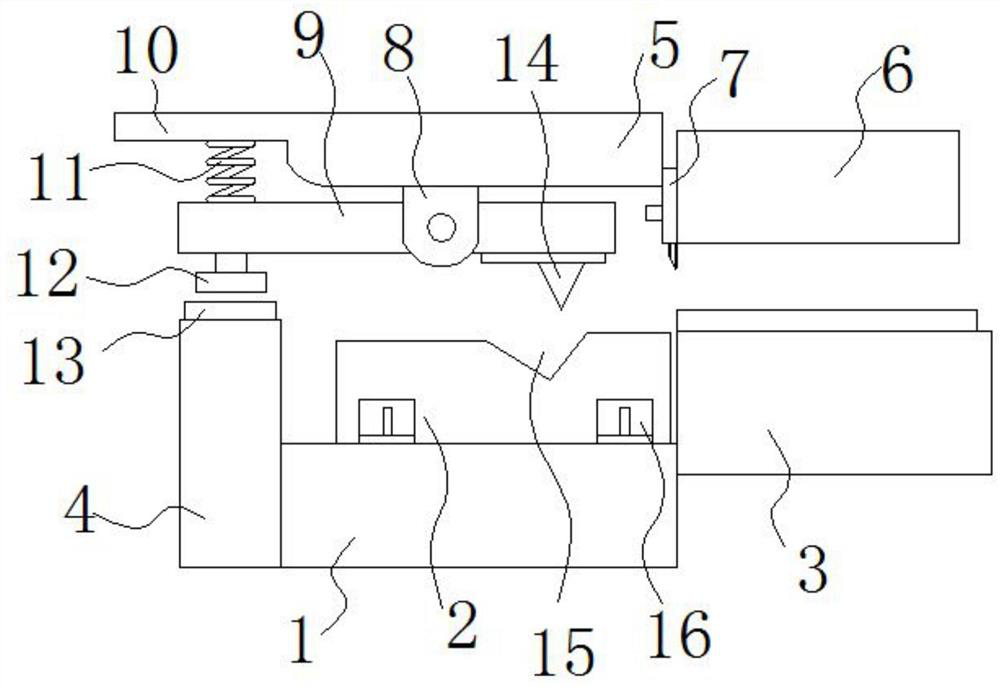
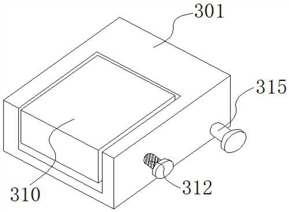
[0044] An embodiment of the present invention provides a stamping die with a rotating scrap knife. The stamping die comprises a lower mold base 1, a lower mold knife block assembly 3, an upper mold base 5, an upper mold pressing block 6, an upper mold knife block assembly 7 and a rotary waste knife assembly. Exemplary, such a...


PUM


Abstract

The invention relates to the technical field of stamping part machining, in particular to a stamping die with a rotary waste cutter and a stamping method thereof. The invention provides the stamping die with the rotary waste cutter, and the stamping die comprises a lower die base, a lower die cutter block assembly, an upper die base, an upper die cutter block assembly and a rotary waste cutter assembly; the lower die cutter block assembly comprises a lower die edge shearing cutter block which is located on one side of the lower die base; an upper die material pressing block is arranged above the lower die edge shearing knife block; a lower die waste cutter is fixedly installed on the lower die base, the upper die base is located over the lower die base, and the upper die cutter block assembly is fixedly installed on the side wall, close to a lower die cutter block assembly shell, of the upper die base; and the rotary waste cutter assembly comprises a rotary waste cutter body, and the rotary waste cutter body is located over the lower die waste cutter. The compatibility of the stamping die can be improved, and the working efficiency is improved.

Description

technical field [0001] The invention belongs to the technical field of stamping parts processing, in particular to a stamping die with a rotating scrap knife and a stamping method thereof. Background technique [0002] In the trimming process of stamping die prior art, the upper die trimming knife of traditional mold is fixed, and the blade in cutting waste area will be higher than the blade in other trimming areas. The edge shape of the edge trimming knife has ups and downs, and the cutting edge of the edge is not synchronized when trimming. [0003] When trimming, the upper mold waste knife first pierces the workpiece, then trims the edge and then trims the edge. Debris is generated when the workpiece is pierced, and the debris will fall to the exposed surface of the workpiece, thereby scratching the surface of the workpiece. Moreover, around the cut-off point, it has a certain impact on the quality of the trimmed section of the workpiece. It will cause defects such as ...

Claims


Application Information

Patent Timeline
Patent Type & Authority Applications(China)
IPC IPC(8): B21D28/14B24B3/36
CPCB21D28/14B24B3/361
Inventor 唐寅周文祥佘方元
Owner 东莞市海洛实业有限公司
Learn More