Round bar center hole machining device

A processing device and center hole technology, applied in positioning devices, metal processing, metal processing equipment, etc., can solve the problems of round bar adjustment, affecting the accuracy and efficiency of processing holes, and high rework rate, so as to prevent shaking and dislocation and improve Practicality and the effect of ensuring accuracy

Pending Publication Date: 2021-10-19
长沙中韵机械设备制造有限公司
View PDF0 Cites 1 Cited by
  • Summary
  • Abstract
  • Description
  • Claims
  • Application Information

AI Technical Summary

Problems solved by technology

[0003] The general round rod center hole processing device has poor fixation to the round rod, which causes the round rod to be easily shaken and dislocated, which affects the accuracy and efficiency of the processing hole, and the drilling of the drilling head to the round rod will generate high temperature due to friction, which is not timely Cooling will affect the service life of the drilling head and the quality of the processed center hole
[0004] (1) The existing compression device for the center hole of the round rod cannot pre-tighten the round rod, and direct pressure to compress the round rod will cause the center of the round rod to shift, making the machining accuracy insufficient, and the existing The cost of the hold-down device is high, and the high rework rate also leads to loss of efficiency
[0005] (2) The existing fixing device for the center hole of the round bar cannot be adjusted according to the different specifications of the round bar, which causes the round bar to easily shake and dislocate, which affects the accuracy and efficiency of the hole processing
[0006] (3) The existing technology usually requires manual blanking of the processed round bar. Due to the heavy weight of the round bar, manual blanking is extremely time-consuming and laborious

Method used


Image

  • Round bar center hole machining device
  • Round bar center hole machining device
  • Round bar center hole machining device

Examples


Embodiment 1

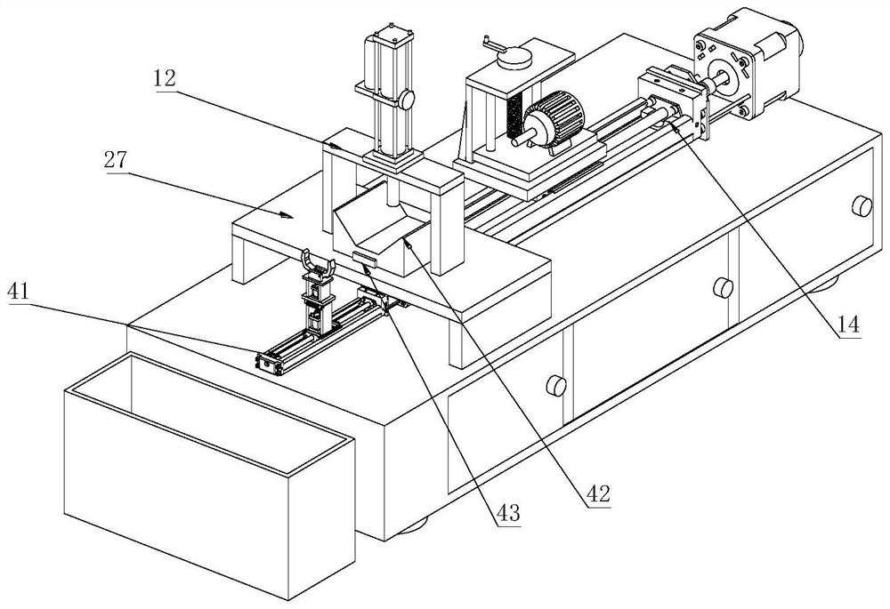
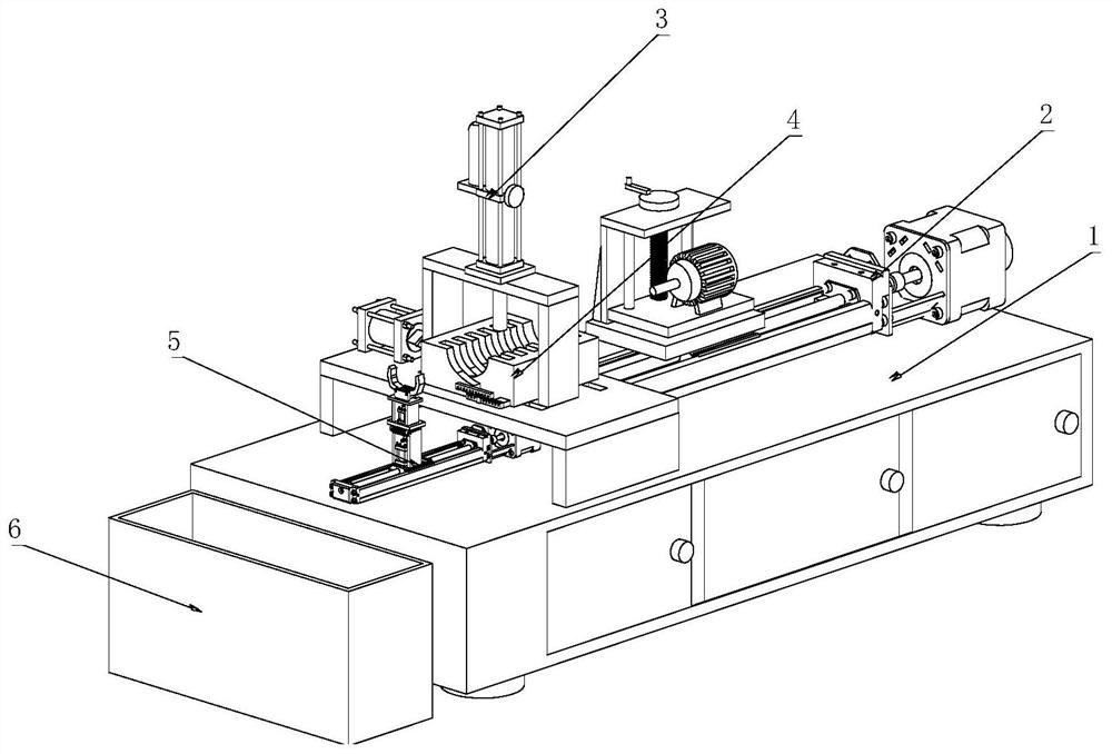
[0045] Such as figure 1 As shown, a round bar center hole processing device includes:

[0046] Workbench 1;

[0047] Compression limit assembly 3, the compression limit is set on one side of the top of workbench 1;

[0048] An adjustable drilling assembly 2, the adjustable drilling assembly 2 is arranged on the side of the top of the workbench 1 away from the compression limit assembly 3;

[0049] Clamping assembly 4, the clamping assembly 4 is arranged below the compression limit assembly 3;

[0050] Automatic blanking assembly 5, the automatic blanking assembly 5 is arranged on the side of the top of the workbench 1 close to the clamping assembly 4;

[0051] Wherein, the compression limit assembly 3 includes a mounting table 27, a fixed frame 12 and a gas-liquid conversion cylinder 11, the mounting table 27 is arranged on one side of the top of the workbench 1, and the fixed frame 12 is arranged on the side of the mounting table 27. At the top, the gas-liquid conversion ...

Embodiment 2

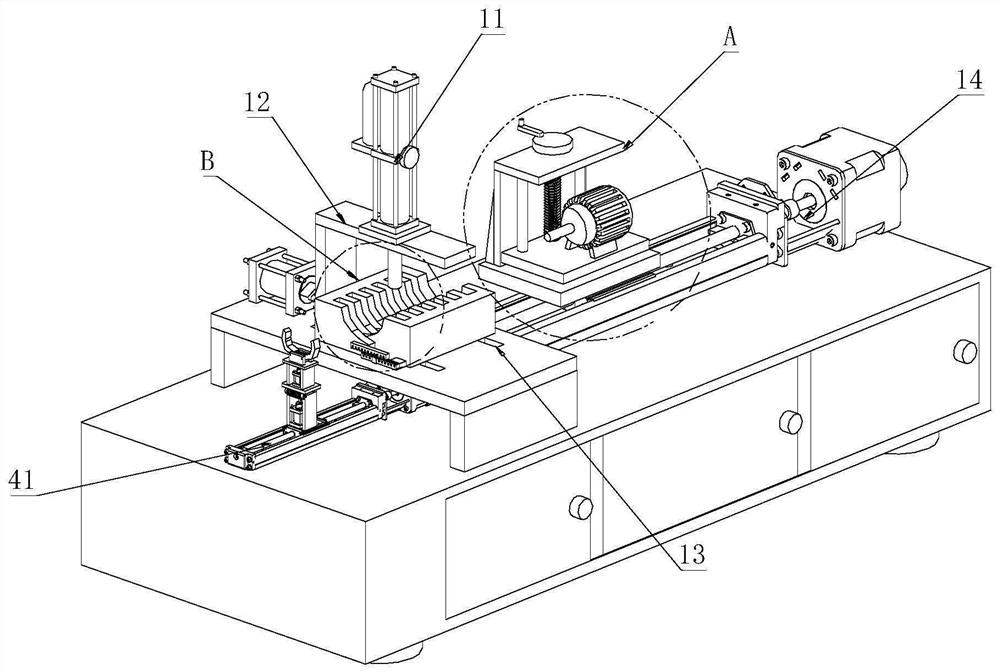
[0054] Such as Figure 2-9 As shown, a round bar center hole processing device includes:

[0055] Workbench 1;

[0056] Compression limit assembly 3, the compression limit is set on one side of the top of workbench 1;

[0057] An adjustable drilling assembly 2, the adjustable drilling assembly 2 is arranged on the side of the top of the workbench 1 away from the compression limit assembly 3;

[0058] Automatic blanking assembly 5, the automatic blanking assembly 5 is arranged on the side of the top of the workbench 1 close to the clamping assembly 4;

[0059] Wherein, the compression limit assembly 3 includes a mounting table 27, a fixed frame 12 and a gas-liquid conversion cylinder 11, the mounting table 27 is arranged on one side of the top of the workbench 1, and the fixed frame 12 is arranged on the side of the mounting table 27. At the top, the gas-liquid conversion cylinder 11 is vertically arranged on the top of the fixed frame 12, and the output shaft of the gas-liq...


PUM


Abstract

The invention relates to the technical field of round bar machining equipment, in particular to a round bar center hole machining device which comprises a workbench, a pressing and limiting assembly, an adjustable drilling assembly, a clamping assembly and an automatic discharging assembly, wherein the pressing and limiting assembly is arranged on one side of the top of the workbench, the adjustable drilling assembly is arranged on the side, away from the pressing and limiting assembly, of the top of the workbench, the clamping assembly is arranged below the pressing and limiting assembly, and the automatic discharging assembly is arranged on the side, close to the clamping assembly, of the top of the workbench. According to the round bar center hole machining device, adjustment can be made in time under the action of the clamping assembly according to different specifications of round bars, so that the round bars are clamped more firmly, the round bars are prevented from shaking and dislocation in the machining process, the machined round bars can be automatically discharged under the action of the automatic discharging assembly, an existing oil cylinder is replaced with a gas-liquid conversion cylinder, cost can be reduced, and the machining precision can be guaranteed.

Description

technical field [0001] The invention relates to the technical field of round bar processing equipment, in particular to a round bar center hole processing device. Background technique [0002] The center hole is a process hole used to process the center of the workpiece. Most shaft parts have a center hole. The main function of the center hole is to serve as a positioning reference for the workpiece during processing and to bear the weight of the workpiece during processing. and cutting force, the existing processing technology for round bars still has the following problems: [0003] The general round rod center hole processing device has poor fixation to the round rod, which causes the round rod to be easily shaken and dislocated, which affects the accuracy and efficiency of the processing hole, and the drilling of the drilling head to the round rod will generate high temperature due to friction, which is not timely Cooling will affect the service life of the drilling hea...

Claims


Application Information

Patent Timeline
Patent Type & Authority Applications(China)
IPC IPC(8): B23B41/00B23Q3/08B23Q7/00
CPCB23B41/00B23Q3/08B23Q7/00
Inventor 周剑锋严龙
Owner 长沙中韵机械设备制造有限公司
Why Eureka
Try Eureka