
Lightning protection device of water level sensor

A water level sensor and lightning protection technology, applied in the installation of cables, buoy liquid level indicators, installation of lighting conductors, etc. Lightning protection and other issues to achieve the effect of preventing lightning damage

Active Publication Date: 2021-10-19
SOUTHERN POWER GRID PEAK LOAD & FREQUENCY REGULATION GENERATING CO LTD +1
View PDF8 Cites 0 Cited by
  • Summary
  • Abstract
  • Description
  • Claims
  • Application Information

AI Technical Summary

Problems solved by technology

[0003] When the float type water level sensor detects the water level, its measuring conduit will be exposed above the water surface, and its electrical components will also be fixed on the water surface through the mounting parts. In thunderstorm weather, lightning strikes often occur. If the lightning falls on the float The electrical components of the type water level sensor or the measuring conduit will make the float type water level sensor unable to detect the water level normally, resulting in the failure to detect the water level height or the water level detection data is incorrect, so that the normal and effective dispatch of energy storage power generation cannot be carried out. Currently, for The lightning protection of the floating ball water level sensor is basically carried out through the external shell. The same position of the shell may be damaged by multiple lightning strikes, so it cannot be protected against lightning

Method used


Image

  • Lightning protection device of water level sensor
  • Lightning protection device of water level sensor
  • Lightning protection device of water level sensor

Examples

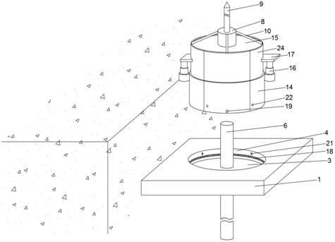
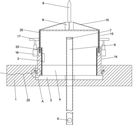

Embodiment Construction

[0024] In order to better understand the technical content of the present invention, a specific embodiment is provided below, and the present invention is further described in conjunction with the accompanying drawings.

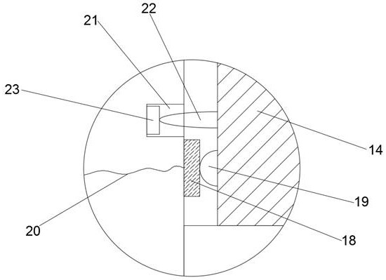
[0025] see Figure 1 to Figure 5 , a lightning protection device for a water level sensor provided by the present invention includes a float type water level sensor, a mounting plate 1, a lightning protection cover, a lightning detection mechanism, a main control unit 2 and an electric turntable 3, and the mounting plate 1 is set On the inner side wall of the reservoir, an installation groove 4 is arranged on its upper surface. The float type water level sensor includes a magnetic float 5, a measuring conduit 6 and a Hall sensor 7. The measuring conduit 6 vertically runs through the installation groove 4. The magnetic The floating ball 5 is arranged inside the part of the measuring conduit 6 below the mounting plate 1, the Hall sensor 7 is arranged on the top...


PUM


Abstract

The invention provides a lightning protection device of a water level sensor. The lightning protection device comprises a floating ball type water level sensor, a mounting plate, a lightning protection cover, a lightning stroke detection mechanism, a main control unit and an electric turntable; the lightning stroke detection mechanism comprises an insulating seat, a vertical metal cylinder, an inclined metal cylinder, a current transformer, a first drainage wire and a second drainage wire; the floating ball type water level sensor is arranged on the mounting plate, when lightning stroke occurs, the vertical metal cylinder and the inclined metal cylinder serve as lightning rods to conduct lightning drainage, the current transformer is arranged in the inclined metal cylinder, and the first drainage wire and the second drainage wire both penetrate through the current transformer; the main control unit can judge the falling point of thunder and lightning according to the direction of current generated by the current transformer, and when the thunder and lightning fall on the inclined metal cylinder, the main control unit can drive the lightning protection cover to rotate through the electric turntable, so that the side which is not struck by lightning or is less struck by lightning is transferred to the side which is more struck by lightning; the same position of the lightning protection cover is prevented from being damaged by multiple lightning strokes.

Description

technical field [0001] The invention relates to the technical field of lightning protection, in particular to a lightning protection device for a water level sensor. Background technique [0002] The hydraulic engineering buildings for flood storage and water regulation can be called reservoirs. The main functions of reservoirs include irrigation, flood control and power generation. Due to seasonal changes, there will be rainy seasons and dry seasons. When reservoirs are used as energy storage hydropower plants, they need The water level of the reservoir is monitored at all times, so the current energy storage reservoir will be equipped with a water level sensor for real-time monitoring of the water level. The commonly used water level sensor is a float-type water level sensor, and the float-type water level sensor includes a magnetic float, a measuring catheter, and a signal unit. , electronic unit, junction box and mounting parts. Generally, the specific gravity of the mag...

Claims


Application Information

Patent Timeline
IPC IPC(8): H02G13/00G01F23/30G01R19/14
CPCH02G13/80H02G13/40H02G13/60G01F23/30G01R19/14
Inventor 高彦明高雄
Owner SOUTHERN POWER GRID PEAK LOAD & FREQUENCY REGULATION GENERATING CO LTD
Learn More