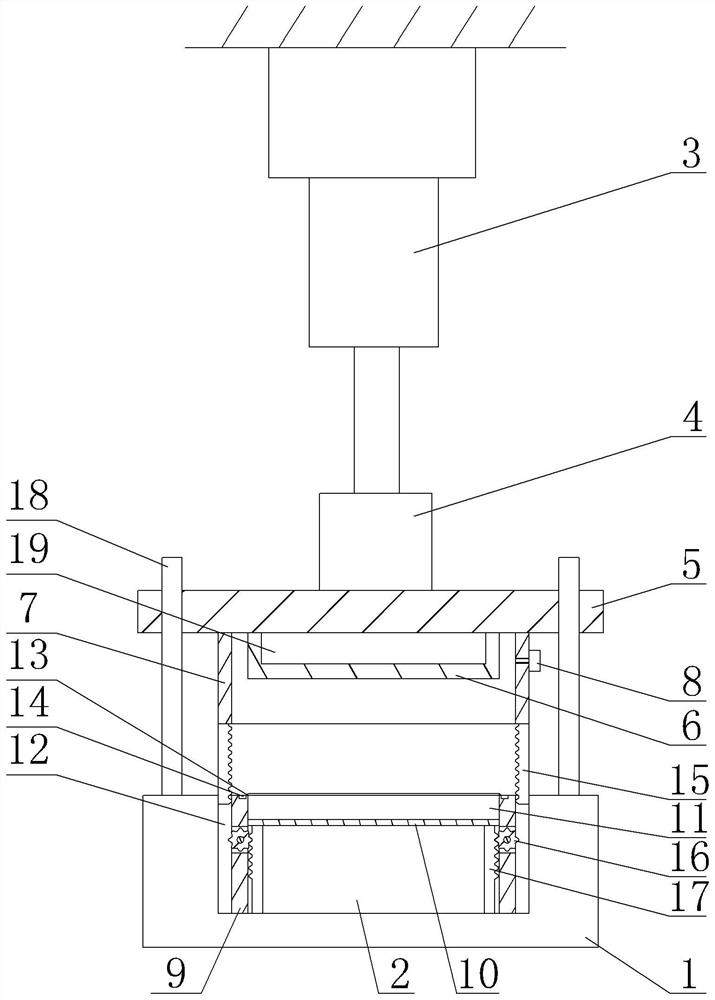
PCB board vacuum lamination device
A PCB board and vacuum layer technology, which is applied in the field of PCB vacuum lamination device, can solve the problems of low alignment accuracy of adjacent PCB boards, air vacuuming, low vacuum degree, etc., so as to avoid circuit extrusion deformation and uniform degree , Adhesive compact effect
- Summary
- Abstract
- Description
- Claims
- Application Information
AI Technical Summary
Problems solved by technology
Method used
Image
Examples
Embodiment 1
[0024] Embodiment 1 is basically as attached figure 1 shown: as figure 1 The shown PCB board vacuum lamination device includes a frame, a support table 1 and a lamination mechanism, and a groove 2 is opened on the support table 1 .
[0025] The lamination mechanism includes a first lamination unit and a second lamination unit. The first lamination unit includes an air cylinder 3, a tension pressure sensor 4 and a sliding plate 5. The air cylinder 3 is fixed on the frame by bolts, and the model of the air cylinder 3 can be selected. CA2-40H-W-100, the sliding plate 5 is connected to the cylinder 3 through the tension pressure sensor 4. The specific connection method can be selected by bolting or welding the tension pressure sensor 4 and the output shaft of the cylinder 3, and the tension pressure sensor 4 and the sliding plate 5 bolts For connection or welding, the model of pull pressure sensor 4 can be selected as WS-CYB-602S-S. The sliding plate 5 is welded with an upper di...
Embodiment 2
[0033]The difference from the first embodiment is that the pushing part includes a support rod and a tension spring (not shown in the figure), a channel is also opened on the side wall of the partition frame 9, and the middle part of the support rod is set at the channel through a pin shaft. , the sealing frame 7 can push the support plate 10 to move upward through the other end of the support rod after contacting with one end of the support rod during the downward movement of the sealing frame 7. The support plate 10 is connected to the bottom of the groove 2 through the tension spring, and the lower end of the tension spring It is welded with the bottom of the groove 2, and the upper end of the tension spring is welded with the support plate 10. When the sealing frame 7 moves upward and separates from the support rod, the other end of the support rod moves down, and the support plate 10 slides down under the action of gravity. Or manually press the circuit board to push the s...
PUM
 Abstract
Description
Claims
Application Information
 - R&D
- Intellectual Property
- Life Sciences
- Materials
- Tech Scout
- Unparalleled Data Quality
- Higher Quality Content
- 60% Fewer Hallucinations
Browse by: Latest US Patents, China's latest patents, Technical Efficacy Thesaurus, Application Domain, Technology Topic, Popular Technical Reports.
© 2025 PatSnap. All rights reserved.Legal|Privacy policy|Modern Slavery Act Transparency Statement|Sitemap|About US| Contact US: help@patsnap.com

