Silage harvesting system and silage harvester

A technology of silage and frame, which is applied in the direction of harvesters, harvesting platforms, agricultural machinery and implements, etc. It can solve the problems of poor material handling capacity, etc., achieve the effect of long throwing distance, increase feeding amount, and realize the effect of front and rear positions

Pending Publication Date: 2021-10-22
LOVOL HEAVY IND CO LTD
View PDF0 Cites 0 Cited by
  • Summary
  • Abstract
  • Description
  • Claims
  • Application Information

AI Technical Summary

Problems solved by technology

[0002] The existing silage material handling system is the integration of simple knapsack-type small silage machine worki...

Method used


Image

  • Silage harvesting system and silage harvester
  • Silage harvesting system and silage harvester
  • Silage harvesting system and silage harvester

Examples


Embodiment 1

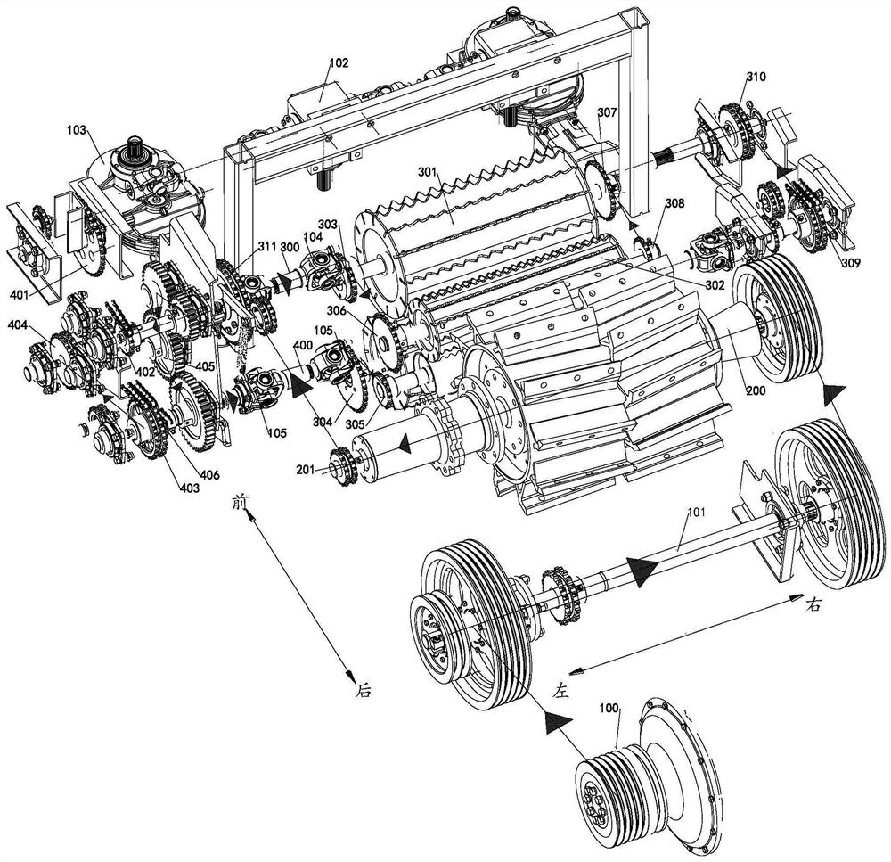
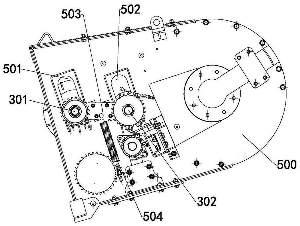
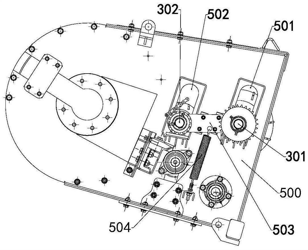
[0064] Such as Figure 1 to Figure 6 As shown, a kind of silage harvesting system of the present embodiment comprises frame 500 and silage header 810 installed on frame 500, conveying module, feeding module 312, chopping module 202, throwing module 811 and throwing barrel 812, the conveying module is located at the rear side of the silage header 810 and transports the harvested crops backwards, the feeding module 312 is located at the rear side of the transporting module and feeds the crops backwards, the chopped The module 202 is located at the rear side of the feeding module 312 and sends the fed crops to the throwing module after being chopped. The throwing cylinder 812 is installed on the rear side of the throwing module 811. The module 811 is located at the rear side of the shredding module 202 and throws the shredded material through the throwing cylinder 812 . It can be thrown into the grass collecting box 813 on the rear side of the silage harvesting system by the thr...

Embodiment 2

[0091] Such as Figure 5 As shown, a kind of green and yellow silage harvester of the present embodiment includes the silage harvesting system, and also includes a fringe harvesting platform 800, and the bottom of the fringe harvesting platform 800 is connected to the silage header by U-shaped bolts 804. On the frame 500 of 810, the rear side top of the ear harvesting platform 800 is connected with the frame 500 of the silage header 810 through the first adjustment pull rod 805, and the bottom middle position of the ear harvesting platform 800 is adjusted by the second adjustment. The pull rod 806 is connected with the frame 500 of the silage header 810; the bottom of the front end of the ear picking header 800 is provided with a plurality of mounting plates 803, and each of the mounting plates 803 is respectively provided with at least one U-shaped Bolts 804 , both ends of the U-shaped bolts 804 are respectively locked and fixed on the installation plate 803 by nuts.

[0092...


PUM


Abstract

The invention relates to a silage harvesting system and a silage harvester. The silage harvesting system comprises a rack, and a silage header, a conveying module, a feeding module, a chopping module, a throwing module and a throwing cylinder which are mounted on the rack, wherein the conveying module is located on the rear side of the silage header and conveys harvested crops backwards, the feeding module is located on the rear side of the conveying module and feeds crops backwards, the chopping module is installed on the rear side of the feeding module and conveys the fed crops backwards to the throwing module after chopping the fed crops, the throwing cylinder is installed on the rear side of the throwing module, and the throwing module is located on the rear side of the chopping module and throws chopped materials through the throwing cylinder. The feeding amount and the conveying efficiency of materials can be improved, the feeding and chopping modules on the rear side can compact and cut off fed stalks, the chopped materials are thrown backwards through the throwing module and the throwing cylinder, the throwing cylinder is located on the middle rear portion of the whole vehicle, the throwing cylinder is in a parabola shape, the throwing distance is long, and the vehicle-following grass receiving function can be realized.

Description

technical field [0001] The invention relates to the technical field related to harvesters, in particular to a silage harvesting system and a silage harvester. Background technique [0002] The existing silage material handling system is the integration of simple knapsack-type small silage machine working parts, the main working parts are all integrated on the header, the layout is simple, and the material handling capacity is poor. Contents of the invention [0003] The technical problem to be solved by the present invention is to provide a silage harvesting system and a silage harvester for the deficiencies of the prior art. [0004] The technical solution of the present invention to solve the above-mentioned technical problems is as follows: a silage harvesting system, including a frame and a silage header installed on the frame, a conveying module, a feeding module, a chopping module, a throwing module and a throwing module. barrel, the conveying module is located at t...

Claims


Application Information

Patent Timeline
IPC IPC(8): A01D43/08A01D47/00A01D69/06
CPCA01D43/086A01D47/00A01D69/06
Inventor 何松吴宗江任星臣赵光军李国栋王岩亮张提昌
Owner LOVOL HEAVY IND CO LTD
Why Eureka
Try Eureka