High-pressure oil pipe with anti-explosion function

A high-pressure oil pipe, functional technology, applied in the field of high-pressure oil pipe with explosion-proof function, can solve the problems of oil pipe burst, inconvenient oil pipe connection, oil pipe damage, etc., and achieve the effect of increasing strength

Inactive Publication Date: 2021-10-22
襄阳宏大飞跃模具有限公司
View PDF0 Cites 0 Cited by
  • Summary
  • Abstract
  • Description
  • Claims
  • Application Information

AI Technical Summary

Problems solved by technology

The existing high-pressure oil pipe is not easy to connect with the oil outlet pipe, and when the oil pressure of the oil outlet pipe enters the high-pressure oil pipe is too high, it may cause damage to the oil pipe, thereby causing the oil pipe to burst. In order to protect the oil pipe, we propose A high-pressure oil pipe with explosion-proof function

Method used


Image

  • High-pressure oil pipe with anti-explosion function
  • High-pressure oil pipe with anti-explosion function
  • High-pressure oil pipe with anti-explosion function

Examples


Embodiment 1

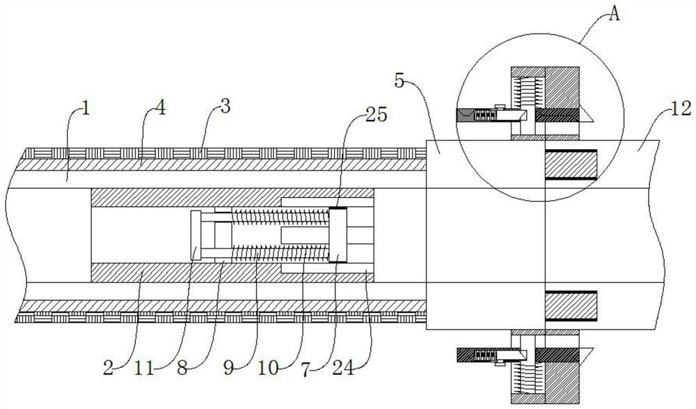
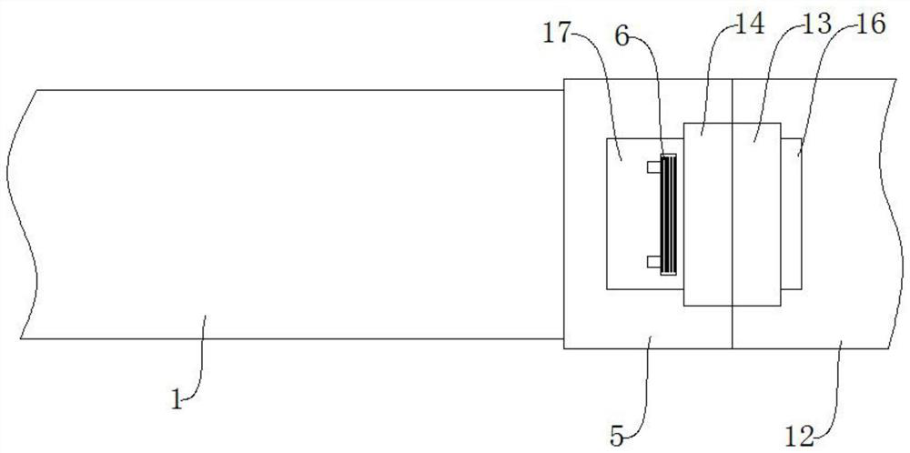
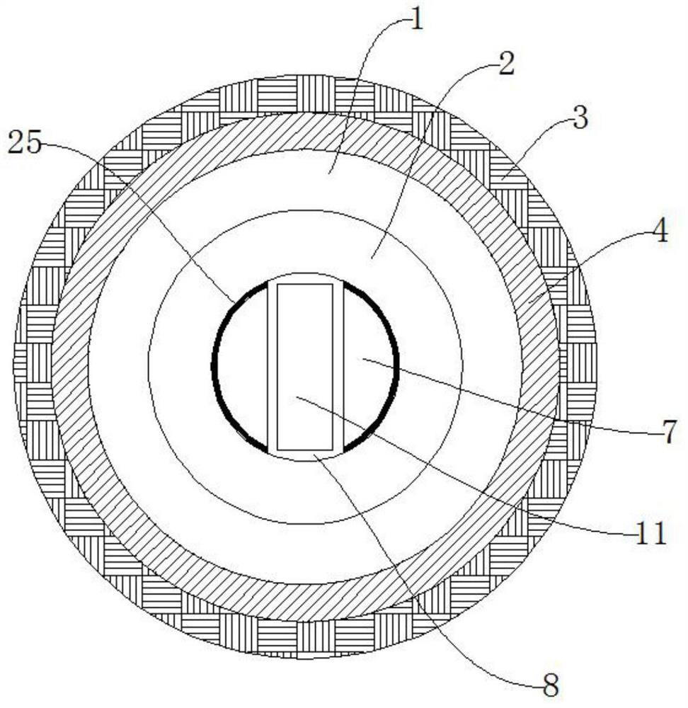
[0024] refer to Figure 1-3 , a high-pressure fuel pipe with explosion-proof function, comprising a fuel pipe main body 1, a pressure-resistant layer 4 is arranged outside the oil pipe main body 1, an outer layer 3 is arranged outside the pressure-resistant layer 4, a connecting pipe 5 is connected to one end of the oil pipe main body 1, and the connecting pipe 5 One end is provided with an oil outlet pipe 12, an insertion mechanism is arranged between the connecting pipe 5 and the oil outlet pipe 12, a limit mechanism is arranged between both sides of the connecting pipe 5 and the oil outlet pipe 12, and a buffer mechanism is arranged in the main body of the oil pipe 1. The mechanism can buffer the liquid entering the main body 1 of the oil pipe, so as to protect the main body 1 of the oil pipe.

Embodiment 2

[0026] refer to Figure 6-7 , as another preferred embodiment of the present invention, the difference from Embodiment 1 is that the pressure-resistant layer 4 includes a polyurethane layer 41 and a steel fiber layer 42, the polyurethane layer 41 is fixed on the outside of the oil pipe main body 1, and the steel fiber layer 42 is fixed on the polyurethane On the outside of layer 41, the outer layer 3 includes an aluminum-plastic composite layer 31 and a PVC layer 32, the aluminum-plastic composite layer 31 is fixed on the outside of the pressure-resistant layer 4, the PVC layer 32 is fixed on the outside of the aluminum-plastic composite layer 31, and the PVC layer 32 is sprayed with anti-corrosion coating. The paint layer 33 can increase the strength of the main body of the oil pipe through the outer layer 3 and the pressure-resistant layer 4 .

Embodiment 3

[0028] refer to figure 1 , as another preferred embodiment of the present invention, the difference from Embodiment 1 is that the insertion mechanism includes an annular slot 22 and an annular flashboard 21, the annular slot 22 is set on the side wall of the oil outlet pipe 12, and the annular flashboard 21 is fixed On one side of the connecting pipe 5, the annular inserting plate 21 is inserted in the annular slot 22, and the contact between the annular inserting plate 21 and the annular slot 22 is fixed with a gasket 23, and the connecting pipe 5 and the oil outlet pipe can be increased by the sealing gasket 23. Tightness between 12.


PUM


Abstract

The invention relates to the technical field of high-pressure oil pipes, in particular to a high-pressure oil pipe with an anti-explosion function. The high-pressure oil pipe with the anti-explosion function comprises an oil pipe main body, wherein a compression-resistant layer is arranged on the outer side of the oil pipe main body, an outer layer is arranged on the outer side of the compression-resistant layer, one end of the oil pipe main body is connected with a connecting pipe, an oil outlet pipe is arranged at one end of the connecting pipe, an inserting mechanism is arranged between the connecting pipe and the oil outlet pipe, limiting mechanisms are arranged between the two sides of the connecting pipe and the oil outlet pipe, and a buffering mechanism is arranged in the oil pipe main body. According to the high-pressure oil pipe, the strength of the oil pipe main body is improved through the outer layer and the compression-resistant layer, and the connecting pipe is connected to the oil outlet pipe through the limiting mechanisms.

Description

technical field [0001] The invention relates to the technical field of high-pressure oil pipes, in particular to a high-pressure oil pipe with an explosion-proof function. Background technique [0002] The high-pressure oil pipe is an integral part of the high-pressure oil circuit. It is required that the oil pipe must withstand a certain oil pressure and have a certain fatigue strength to ensure the sealing requirements of the pipeline. The high-pressure oil pipe for vehicles mainly appears in high-pressure injection diesel engines and high-pressure injection direct injection. In a gasoline engine, it can withstand the oil pressure required for the engine to run. The oil pipe is composed of a steel wire wound skeleton layer and an oil-resistant and corrosion-resistant synthetic rubber inside and outside. Oil pipes are mainly used for excavators, loaders, rollover trucks, hydraulic boosters, hydraulic supports, cement delivery pipes, agricultural irrigation hoses, construct...

Claims


Application Information

Patent Timeline
Patent Type & Authority Applications(China)
IPC IPC(8): F16L9/128F16L47/12F16L57/00F02M55/00F02M55/02F16L58/02
CPCF16L9/128F16L47/12F16L57/00F02M55/02F02M55/005F16L58/02
Inventor 魏少波赵刚代辉
Owner 襄阳宏大飞跃模具有限公司
Why Eureka
Try Eureka