Combustion chamber shell machining benchmark design method

A technology of processing benchmarks and design methods, applied in measuring devices, instruments, optical devices, etc., can solve the problems of inability to identify in advance, increase the workload of calibration, etc., and achieve the effect of reducing the time for repeated calibration and reducing errors

Active Publication Date: 2021-10-22
SHANGHAI XINLI POWER EQUIP RES INST
View PDF13 Cites 2 Cited by
  • Summary
  • Abstract
  • Description
  • Claims
  • Application Information

AI Technical Summary

Problems solved by technology

At present, on the processing equipment, after the parts are clamped, each processing surface is calibrated, and the processing standard is determined repeatedly. As the complexity of the processed parts increases, the workload of calibration also increases.
For the deformation of the combustion chamber casing beyond the margin range, it cannot be identified in advance

Method used


Image

  • Combustion chamber shell machining benchmark design method
  • Combustion chamber shell machining benchmark design method
  • Combustion chamber shell machining benchmark design method

Examples


Embodiment Construction

[0025] Exemplary embodiments of the present disclosure will be described in more detail below with reference to the accompanying drawings. Although exemplary embodiments of the present disclosure are shown in the drawings, it should be understood that the present disclosure may be embodied in various forms and should not be limited by the embodiments set forth herein. Rather, these embodiments are provided for more thorough understanding of the present disclosure and to fully convey the scope of the present disclosure to those skilled in the art. It should be noted that, in the case of no conflict, the embodiments of the present invention and the features in the embodiments can be combined with each other. The present invention will be described in detail below with reference to the accompanying drawings and examples.

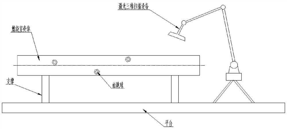
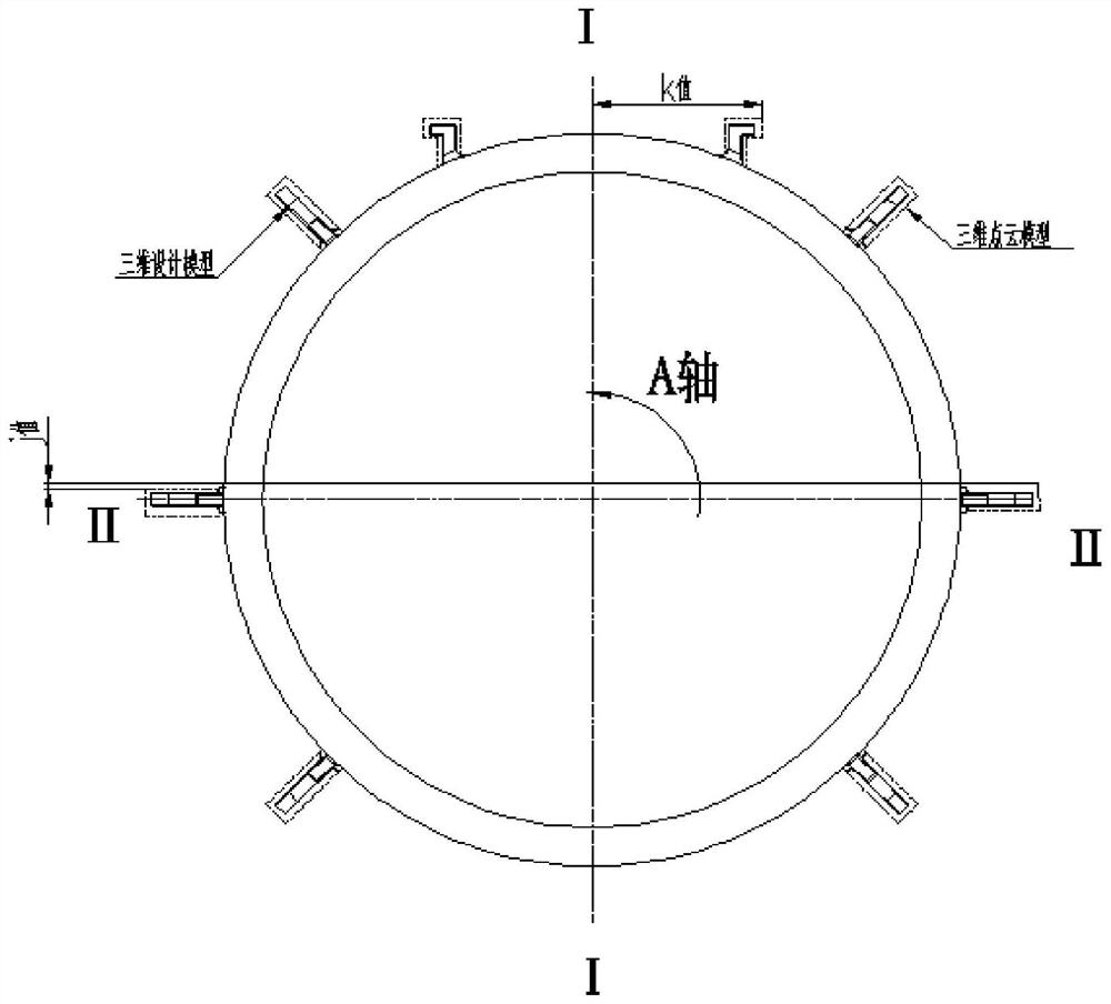
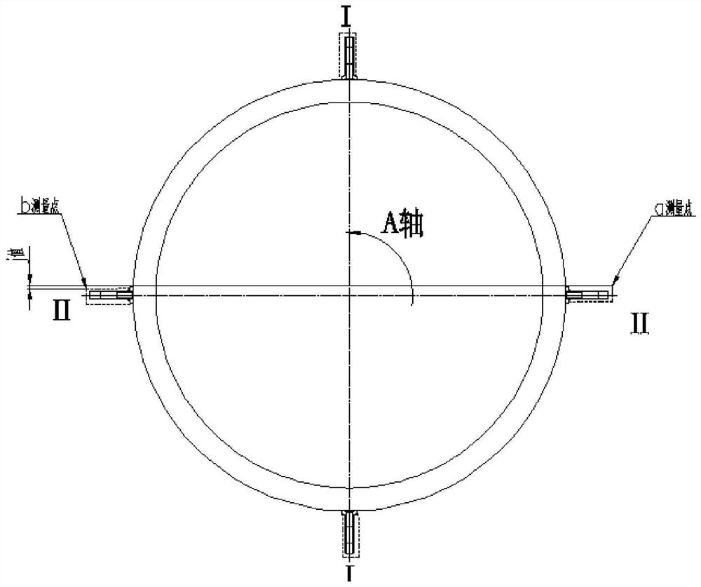
[0026] This embodiment provides a method for designing a benchmark for machining a combustion chamber housing, including the following steps:

[0027] Step 1...


PUM


Abstract

The invention discloses a combustion chamber shell machining benchmark design method. The method comprises the following steps: firstly, placing a combustion chamber shell with an external hanging piece arranged on an outer surface and a laser three-dimensional scanner on a platform; 2, measuring the combustion chamber shell by using a laser three-dimensional scanner to generate a three-dimensional point cloud model; fitting the three-dimensional point cloud model with a preset three-dimensional design model of the combustion chamber shell; 3, taking the central vertical line of the three-dimensional design model as I-I reference, and taking the central horizontal line of the three-dimensional design model as II-II reference; and rotating the three-dimensional point cloud model around the central axis, and when the external hanging piece models of the three-dimensional design model are all located in the size range of the external hanging piece models of the three-dimensional point cloud model, determining a machining reference transmission value through a method of distance between a vertical plane and the central axis. The machining efficiency is improved.

Description

technical field [0001] The invention belongs to the technical field of combustion chamber casing processing, and in particular relates to a design method for processing a combustion chamber casing reference. Background technique [0002] In the process of processing, the combustion chamber shell adopts multiple processes, such as welding and heat treatment. When finishing the hanger, there are deformations and other situations, especially the material is high hardness, which cannot be enlarged without limit in the control of the finishing allowance. Therefore, in the finishing process, the machining reference position needs to ensure that all the machining surfaces are within the allowance range. At present, on the processing equipment, after the parts are clamped, each processing surface is calibrated, and the adjustment is repeated back and forth to determine the processing benchmark. As the complexity of the processed parts increases, the workload of calibration also inc...

Claims


Application Information

Patent Timeline
Patent Type & Authority Applications(China)
IPC IPC(8): G01B11/24G01B11/16
CPCG01B11/24G01B11/16
Inventor 徐利军段佳倩朱立坚李睿张建赵亦东强锦霖吴启亮单秀峰高珺
Owner SHANGHAI XINLI POWER EQUIP RES INST
Why Eureka
Try Eureka