
Air temperature observation instrument

An observation instrument and air temperature technology, which is applied in the field of temperature observation instruments, can solve the problems of reducing the response speed of temperature measuring elements, measurement errors of internal temperature measuring elements, and difficulty in measuring atmospheric temperature in real time, so as to facilitate disassembly and cleaning, increase airflow speed, and improve Effect of Gas Velocity

Active Publication Date: 2021-10-22
NANJING UNIV OF INFORMATION SCI & TECH
View PDF9 Cites 0 Cited by
  • Summary
  • Abstract
  • Description
  • Claims
  • Application Information

AI Technical Summary

Problems solved by technology

It is difficult for the shutters and radiation shields to completely block all kinds of radiation, and there will still be a certain amount of radiation heating, which will cause the air around the shutters and radiation shields to be heated and flow into them, causing measurement errors of the internal temperature measuring components. The exchange of airflow inside and outside the radiation shield will be affected by its structure, which will further increase the measurement error and reduce the response speed of the temperature measuring element
The measurement error of the temperature measuring components inside the shutter box and the radiation shield is on the order of 1°C. It is difficult for the existing meteorological temperature observation instruments to measure the atmospheric temperature accurately and in real time. Therefore, a temperature observation instrument is proposed

Method used


Image

  • Air temperature observation instrument
  • Air temperature observation instrument
  • Air temperature observation instrument

Examples


Embodiment

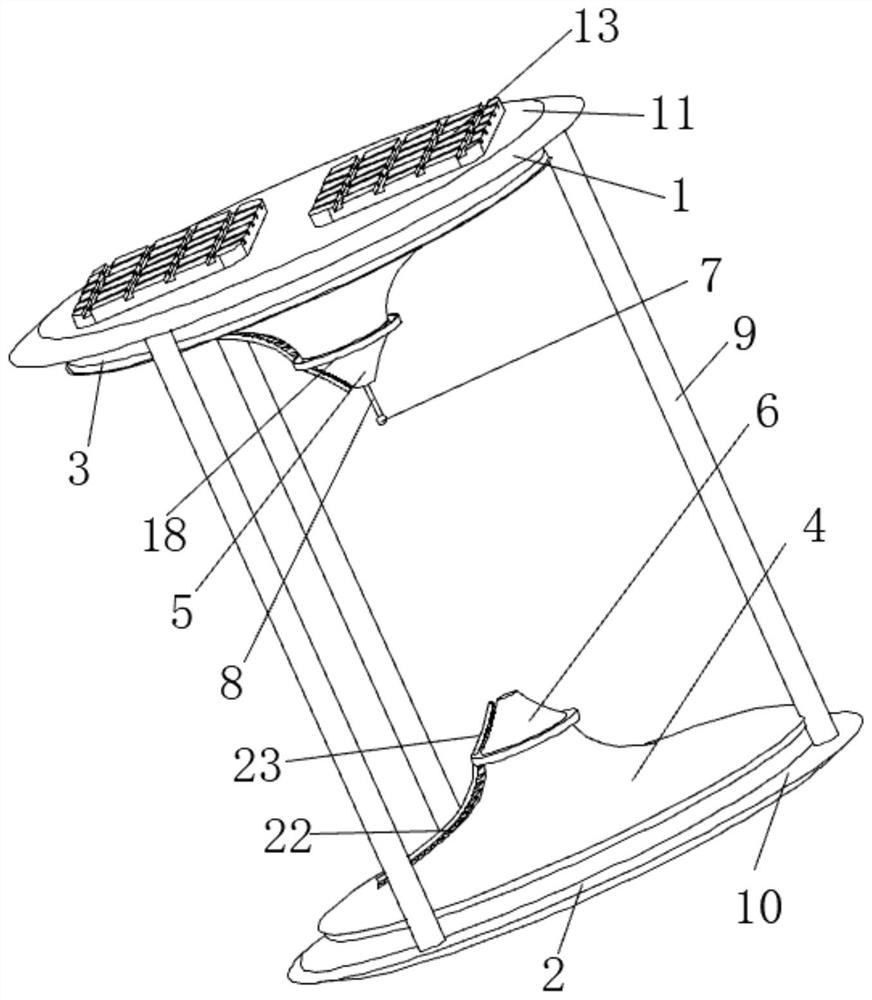
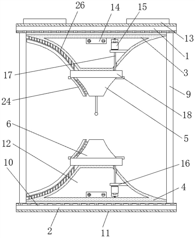
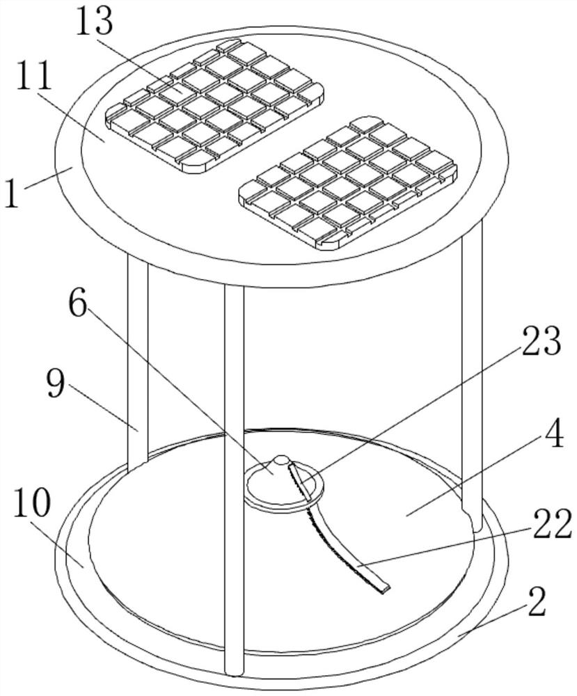
[0023] see Figure 1-5 , the present invention provides a technical solution: a temperature observation instrument, comprising a first shading plate 1 and a second shading plate 2, three fixed columns 9 are fixedly connected between the first shading plate 1 and the second shading plate 2, the second A first curved guide platform 3 is provided below a light shielding plate 1, a second curved guide platform 4 is provided above the second shade plate 2, and a first annular guide platform is fixedly connected to the bottom of the first curved surface guide platform 3. plate 5, the bottom of the first annular deflector 5 is fixedly connected with a heat-insulating suspension rod 8, the bottom of the heat-insulated suspension rod 8 is equipped with a temperature measuring probe 7, and the top of the second curved surface deflector 4 is fixedly connected with a second annular The deflector 6, the top of the first shading plate 1 and the bottom of the second shading plate 2 are all p...


PUM


Abstract

The invention discloses an air temperature observation instrument which is characterized in that the bottom of a first annular flow guide plate is fixedly connected with a heat insulation suspension rod, the bottom of the heat insulation suspension rod is provided with a temperature measurement probe, the top of a second curved surface flow guide table is fixedly connected with a second annular flow guide plate, and the top of a first light shielding plate and the bottom of a second light shielding plate are both provided with mirror surface reflective coatings, and the bottom of the first light shielding plate and the top of the second light shielding plate are each provided with a matte surface light absorption coating. The surface, facing the sun, of the first light shielding plate and the surface, facing the underlying surface, of the second light shielding plate are both plated with the mirror surface light reflecting coatings with the high light reflecting characteristic, so that direct radiation of the sun and reflection radiation and long-wave radiation of the underlying surface are blocked to a large extent, the surface, facing the lower pad surface, of the first light shielding plate and the surface, facing the sun, of the second light shielding plate are coated with high-absorptivity matte surface light absorption coatings, and the influence of secondary radiation caused by various kinds of radiation entering the device on the temperature measuring probe is effectively reduced.

Description

technical field [0001] The invention relates to the field of meteorological instruments, in particular to a temperature observation instrument. Background technique [0002] Due to the influence of direct solar radiation, reflected radiation from the underlying surface, scattered radiation, long-wave radiation, etc., the temperature observation instruments used in meteorological stations will produce large measurement errors. To reduce the error, the temperature observation instruments are usually equipped with louvers A box or a radiation shield to prevent the temperature measuring element from being exposed to various radiations. It is difficult for the shutters and radiation shields to completely block all kinds of radiation, and there will still be a certain amount of radiation heating, which will cause the air around the shutters and radiation shields to be heated and flow into them, causing measurement errors of the internal temperature measuring components. The excha...

Claims


Application Information

Patent Timeline
IPC IPC(8): G01K13/024G01W1/00
CPCG01K13/024G01W1/00Y02E10/50
Inventor 杨杰刘清惓姜帆丁仁惠葛祥建王帅
Owner NANJING UNIV OF INFORMATION SCI & TECH
Learn More