Test load device for simulating cell

A technology for testing loads and batteries, applied in the detection field, can solve problems such as high cost, explosion, and inability to use real battery packs, so as to avoid accidents, facilitate testing, and reduce costs

Active Publication Date: 2021-10-22
广东中创智腾技术服务有限公司
View PDF5 Cites 0 Cited by
  • Summary
  • Abstract
  • Description
  • Claims
  • Application Information

AI Technical Summary

Problems solved by technology

In reality, how to check whether the new equipment meets the technical requirements agreed in advance requires on-site testing. Since the real battery pack can only do a single experiment, its cost is relatively high, and the testers need to operate close to the test during the verification process. The battery pack may explode during the test process, so the real battery pack cannot be used for verification during the test
[0005] As a result, a test load device that simulates a battery cell appears. It simply uses a steel plate or an aluminum plate as a load. Even if the extrusion force can be achieved, the extrusion force and deformation cannot be obtained because the steel plate and the aluminum plate are solid. The displacement relationship cannot satisfy the experimental

Method used


Image

  • Test load device for simulating cell
  • Test load device for simulating cell
  • Test load device for simulating cell

Examples


Embodiment 1

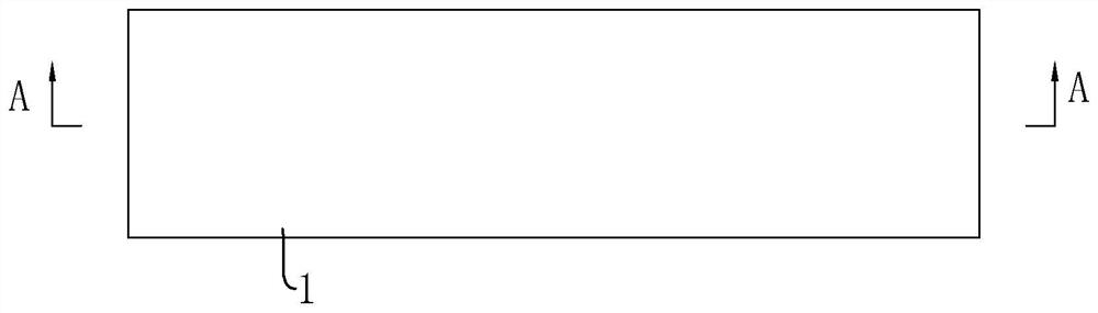
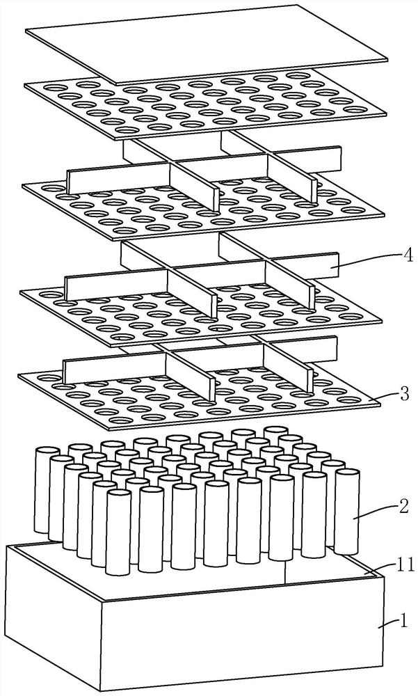
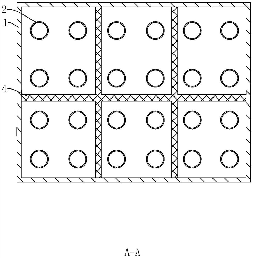
[0037] refer to figure 1 and figure 2 , a test load device for simulating battery cells, comprising a housing 1, a housing 1 is provided with a accommodating cavity 11, a supporting unit is provided in the accommodating cavity 11, the supporting unit is connected to the side wall of the housing 1, the supporting unit and The shell 1 constitutes a test load device that simulates the cell for testing, and tests its resistance to pressure and deformation. The placement direction of the shell 1 during the test is defined as the up-down direction, and the corresponding support unit is arranged in the up-down direction.

[0038] refer to figure 1 and figure 2 , in this embodiment, the casing 1 is in a closed structure, the casing 1 is composed of a bottom plate, a top plate and a side plate, the side plate is bent to form a structure with a back-shaped cross section, and the bottom plate, the top plate and the side plate are enclosed to form an accommodating cavity 11, the casi...

Embodiment 2

[0044] The difference from Embodiment 1 is that the arrangement of the plurality of support tubes 2 is different. With one support tube 2 as the center, the rest of the support tubes 2 are circumferentially distributed outside the center support tube 2 .

Embodiment 3

[0046] The difference from Embodiment 1 is that the structure of the second positioning unit is different. The second positioning unit includes a first positioning ring 5 and a plurality of third positioning plates 6, and the plurality of third positioning plates 6 are evenly circumferentially connected to the first positioning ring. An outer side wall of a positioning ring 5, the first positioning ring 5 and a plurality of third positioning plates 6 are located between adjacent first positioning plates 3, wherein the support tube 2 near the center passes through the first positioning ring 5, and the corresponding support The tubes 2 are located between adjacent third positioning plates 6 .


PUM


Abstract

The invention discloses a test load device for simulating a cell, and the device comprises: a shell which is internally provided with an accommodation cavity; and a supporting unit which is located in the containing cavity, wherein the supporting unit is connected to one opposite side wall of the shell. The supporting unit is placed in the shell, the internal structure achieves similar extrusion resistance and deformation resistance in the test load device for simulating the cell, accidents of a tester are avoided during an experiment, the test cost is reduced, and a supplier and a user can test equipment on site through the test load device for simulating the cell, and the effect of facilitating testing is achieved.

Description

technical field [0001] The invention relates to the technical field of detection, in particular to a test load device for simulating a battery cell. Background technique [0002] Countries around the world are paying more and more attention to environmental protection, thus vigorously supporting the development of various new energy technologies. Automobile exhaust is an important source of air pollution, and major automobile manufacturers have begun to study new energy vehicles. As a kind of new energy vehicles, electric vehicles have truly achieved zero exhaust emissions. However, electric vehicles face more safety hazards than traditional vehicles, and more stringent safety monitoring standards must be implemented. [0003] The power battery is one of the core components of a pure electric vehicle. It not only involves the time-consuming and longest mileage of a full charge, but also the safety of the vehicle under various complex driving conditions. Therefore, the safe...

Claims


Application Information

Patent Timeline
Patent Type & Authority Applications(China)
IPC IPC(8): G01N3/08G01N3/02G01N3/04
CPCG01N3/08G01N3/02G01N3/04G01N2203/0019
Inventor 刘虹君石雄毅刘展叶春南
Owner 广东中创智腾技术服务有限公司
Why Eureka
Try Eureka