Three-component downhole magnetometer based on high-temperature digital fluxgate
A three-component, fluxgate technology, applied in the direction of electric/magnetic detection for well logging records, can solve the problems of inapplicability, low precision, large steering difference, etc., to facilitate data processing and application, and improve sensitivity The effect of measurement accuracy
- Summary
- Abstract
- Description
- Claims
- Application Information
AI Technical Summary
Problems solved by technology
Method used
Image

Examples
Embodiment Construction
[0027] The technical solutions in the embodiments of the present invention will be clearly and completely described below in conjunction with the accompanying drawings in the embodiments of the present invention. Obviously, the described embodiments are only some of the embodiments of the present application, not all of them. Based on the embodiments in this application, all other embodiments obtained by those skilled in the art without making creative efforts belong to the scope of protection of this application.
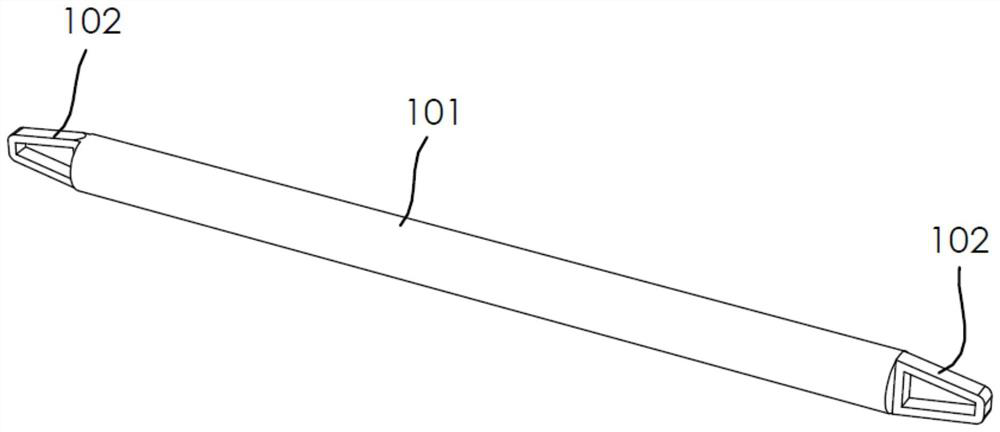
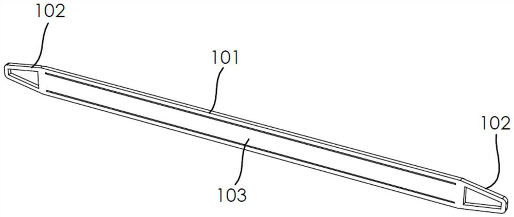
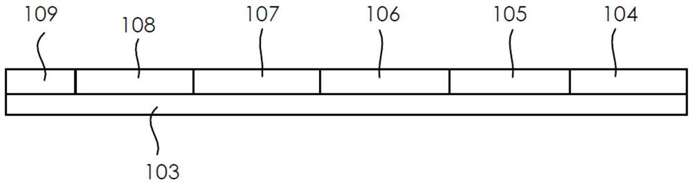
[0028] Such as Figure 1 to Figure 5 As shown, the embodiment of the present invention provides a three-component well magnetometer based on a high-temperature digital fluxgate, which is suitable for deep ore prospecting, specifically, the three-component well magnetometer based on a high-temperature digital fluxgate The three-component well magnetometer of the high-temperature digital fluxgate can be used for mineral exploration in mines with an aperture of more t...
PUM
 Abstract
Description
Claims
Application Information