Equipment debugging method and electronic equipment

A technology of electronic equipment and equipment, which is applied in the computer field, can solve problems such as interfering with the work of debugging personnel, reducing equipment debugging efficiency, and debugging information can no longer receive switching commands from debugging personnel, so as to improve debugging efficiency and reduce the burden on debugging personnel.

Pending Publication Date: 2021-10-22
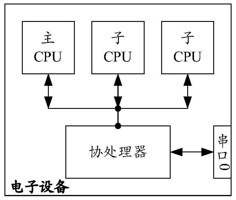
HANGZHOU DPTECH TECH
View PDF6 Cites 0 Cited by
  • Summary
  • Abstract
  • Description
  • Claims
  • Application Information

AI Technical Summary

Problems solved by technology

For example, when a switching command for any target CPU is input to the coprocessor through the serial port, if the target CPU is not faulty, the debugging information of the target CPU can be output through the serial port; When the target CPU fails, the debugging information cannot be output through the serial port and the switching command input by the debugging personnel can no longer be received, and if it is necessary to continue to output the debugging information of other CPUs, it is necessary to restart the whole machine to continue the above-mentioned Debugging process
Therefore, it greatly interferes with the work of debugging personnel and reduces the efficiency of equipment debugging

Method used


Image

  • Equipment debugging method and electronic equipment
  • Equipment debugging method and electronic equipment
  • Equipment debugging method and electronic equipment

Examples


Embodiment Construction

[0019] Reference will now be made in detail to the exemplary embodiments, examples of which are illustrated in the accompanying drawings. When the following description refers to the accompanying drawings, the same numerals in different drawings refer to the same or similar elements unless otherwise indicated. Implementations described in the following exemplary embodiments do not represent all implementations consistent with one or more embodiments of this specification. Rather, they are merely examples of apparatuses and methods consistent with aspects of one or more embodiments of the present specification as recited in the appended claims.

[0020] It should be noted that in other embodiments, the steps of the corresponding methods are not necessarily performed in the order shown and described in this specification. In some other embodiments, the method may include more or less steps than those described in this specification. In addition, a single step described in this...


PUM


Abstract

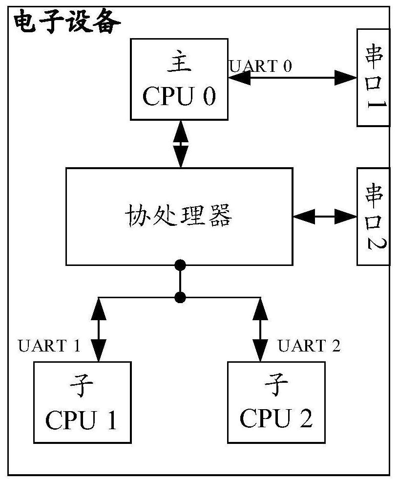
The invention provides an equipment debugging method and electronic equipment. The method is applied to the electronic equipment provided with a main CPU, sub-CPUs and a coprocessor, the electronic equipment is provided with a first serial port and a second serial port which are used for external debugging, the first serial port is connected with the main CPU, the second serial port is connected with the coprocessor, and the coprocessor is connected with the sub-CPUs and the main CPU. When a main CPU of the electronic equipment receives a debugging command which is input through a first serial port and aims at a target sub-CPU, a coprocessor is notified to associate a second serial port with the target sub-CPU; and the coprocessor of the electronic equipment outputs the debugging information of the target sub-CPU to the outside through the second serial port after receiving a notification that the main CPU associates the second serial port with the target sub-CPU. The two serial ports are respectively arranged to realize command receiving and information output functions, so that the problem that the whole machine must be restarted due to the fact that commands cannot be received and debugging cannot be continued after the serial ports are switched to the fault sub-CPU in the prior art is solved, and the equipment debugging efficiency is improved.

Description

technical field [0001] One or more embodiments of this specification relate to the field of computer technology, and in particular, to a device debugging method and an electronic device. Background technique [0002] With the development of technology and the improvement of demand, more and more devices adopt the distributed management architecture. Under this architecture, in addition to the main CPU in the device, subsystems such as fan modules and the sub-boards assembled are also configured with their own Sub-CPU. When debugging the device of the distributed management architecture, how to obtain the debugging information of the main CPU and the sub-CPU in the device becomes an urgent problem to be solved. [0003] In related technologies, generally, an external debugging serial port is configured on the device, the serial port is connected to a coprocessor, and the coprocessor is connected to debugging interfaces of all CPUs. The debugger issues a switching command to...

Claims


Application Information

Patent Timeline
Patent Type & Authority Applications(China)
IPC IPC(8): G06F11/22G06F11/273G06F11/20
CPCG06F11/2242G06F11/2733G06F11/202
Inventor 杨淦宇陈宁秦德楼
Owner HANGZHOU DPTECH TECH
Why Eureka
Try Eureka