Input torque detecting device of electric boosting vehicles

A technology of input torque and electric power assist, applied in measurement devices, vehicle components, vehicle gearboxes, etc., can solve the problems of unable to provide motor auxiliary power, unable to detect time difference, etc., to achieve easy maintenance and installation operations, space saving, installation The effect of easy work

Inactive Publication Date: 2004-01-21
HONDA MOTOR CO LTD
View PDF1 Cites 1 Cited by
  • Summary
  • Abstract
  • Description
  • Claims
  • Application Information

AI Technical Summary

Problems solved by technology

In this way, as long as the pulse signals are not output from the two rotation sensors, the above-mentioned time difference cannot be detected. Therefore, in the state where the pedal sprocket does not rotate and the vehicle speed = 0, it is impossible to detect the input torque. When the state starts to step on the crank pedal, it provides the auxiliary power of the motor

Method used


Image

  • Input torque detecting device of electric boosting vehicles
  • Input torque detecting device of electric boosting vehicles
  • Input torque detecting device of electric boosting vehicles

Examples


Embodiment Construction

[0026] Embodiments of the invention are explained below on the basis of the illustrated exemplary embodiment of the invention.

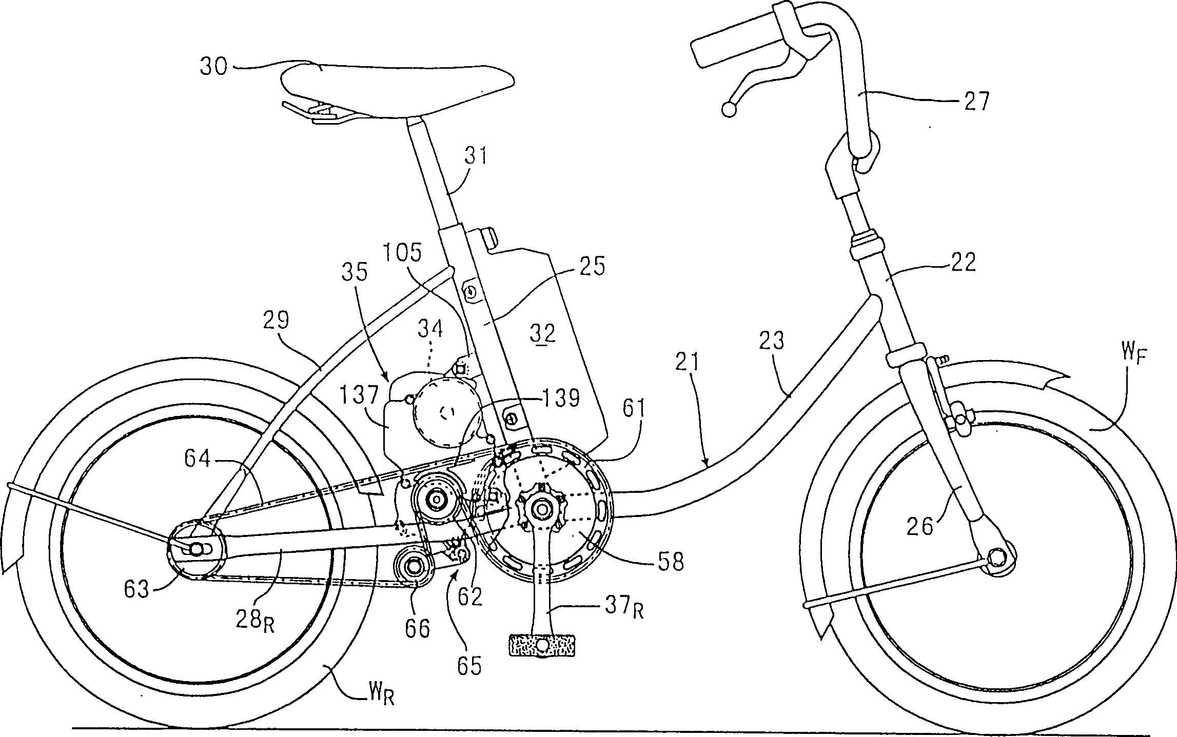
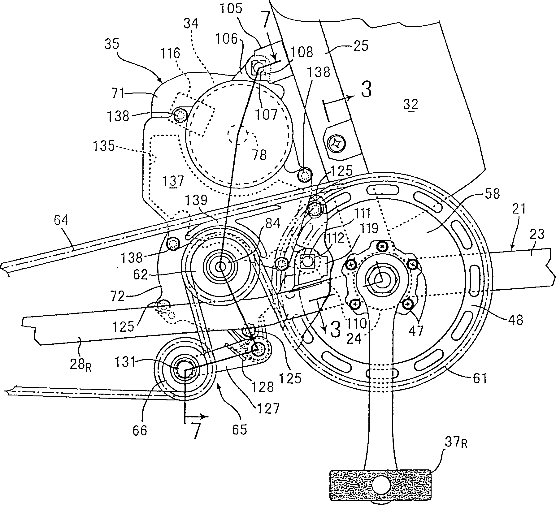
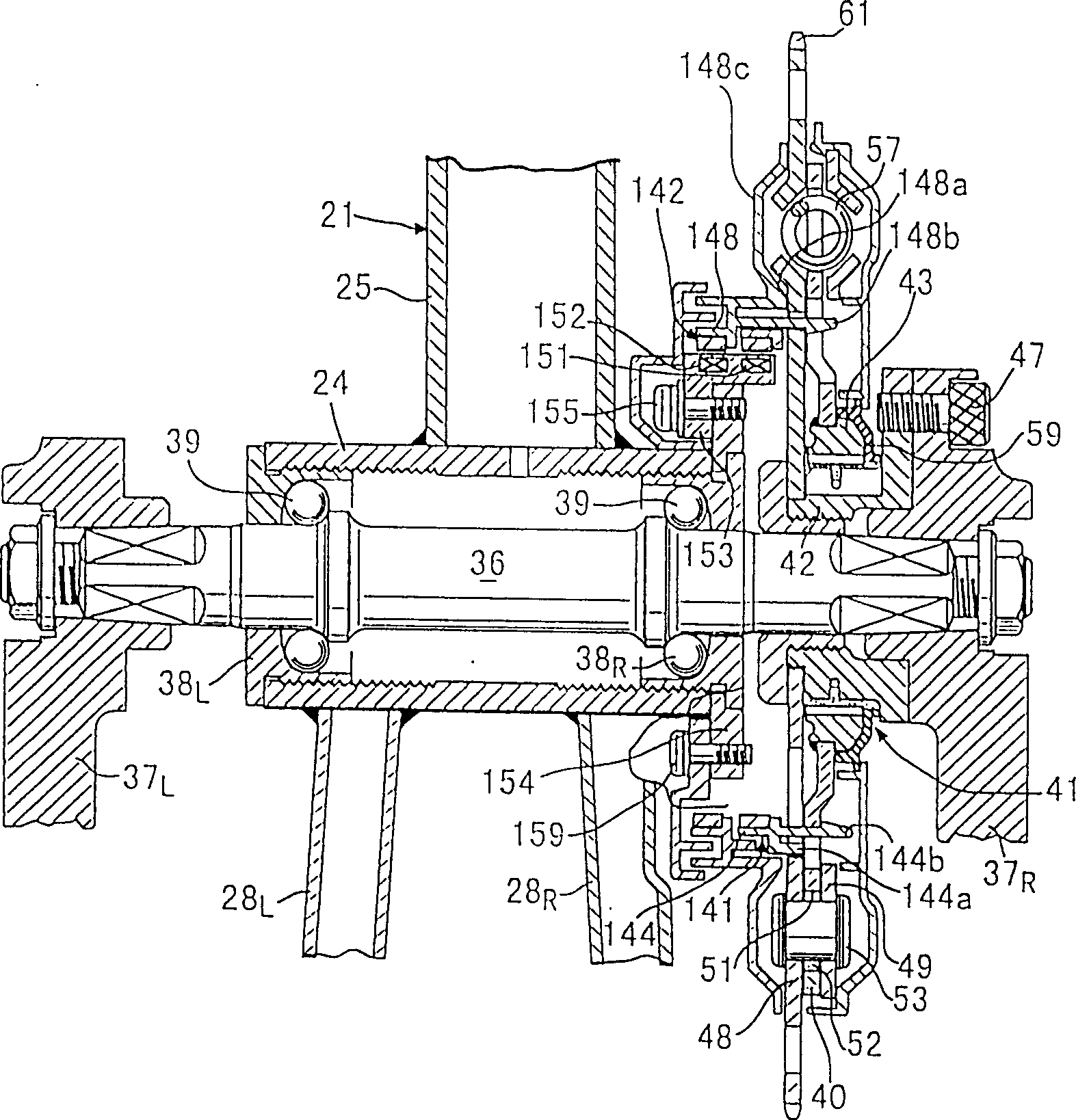
[0027] Figure 1 to Figure 14 The first embodiment of the electric power-assisted bicycle adapted to the present invention is shown, figure 1 is a side view of an electric assist bicycle, figure 2 Yes figure 1 Enlarged view of main part, image 3 Yes figure 2 A sectional view of the 3-3 section, Figure 4 Yes image 3 Enlarged view of main part, Figure 5 Yes Figure 4 A sectional view of the 5-5 section, Image 6 Yes Figure 4 A sectional view of section 6-6, Figure 7 is figure 2 An enlarged cross-sectional view of section 7-7, Figure 8 Yes Figure 4 sectional view of the 8-8 section, Figure 9 Yes Figure 4 The cross-sectional view of the 9-9 section, FIG. 10 is a schematic diagram showing the relative arrangement of the first sensor and the magnetic poles of the first magnetic ring, Figure 11 FIG. 12 is a schematic diagram for ...


PUM


Abstract

The invention is to detect an input torque so as to quickly give an auxiliary power to a driving wheel at the start of operation input from the stopped state of a vehicle, in an electric auxiliary vehicle capable of applying the auxiliary power corresponding to the input torque to the driving wheel from an electric motor. A first magnetic ring rotates along with a first rotary body synchronous with an input operation member. A plurality of N poles and S poles of the first magnetic ring are detected by a plurality of first sensors at fixed positions. A second magnetic ring rotates along with a second rotary body synchronous with a driving wheel, and a plurality of N poles and S poles of the second magnetic ringare detected by a plurality of second sensors of fixed positions. A control unit judges a rotational phase difference of the first and second rotary bodies by a combination pattern of detection signals of the first and second sensors. At the same time, the control unit recognizes the rotational phase difference as an input torque, thereby controlling the operation of an electric motor.

Description

technical field [0001] The present invention relates to an input torque detection device for detecting an input torque applied to an input operating member of an electric power assisted vehicle including an input operating member and a motor, the input operating member being detected by human power for rotationally driving driving wheels In operation, the motor applies auxiliary power to the drive wheels corresponding to the input torque applied to the input operating member. Background technique [0002] Conventionally, an input torque detection device for detecting the input torque of an electric power-assisted bicycle is known, for example, the structure disclosed in Japanese Patent Application Laid-Open No. 8-313376. [0003] However, the above-described conventional technology uses the first rotation sensor to detect the rotation of the crank pedal, and the second rotation sensor to detect the rotation of the pedal sprocket. In this way, as long as pulse signals are no...

Claims


Application Information

Patent Timeline
Patent Type & Authority Patents(China)
IPC IPC(8): G01L3/14B62M6/45B62M6/50
CPCB62M6/55B62M6/45B62M6/70B62M6/50
Inventor 三浦信夫三浦静止
Owner HONDA MOTOR CO LTD
Why Eureka
Try Eureka