Optical machine definition adjusting and testing method and system

A high-definition, optical-mechanical technology, applied in television, electrical components, image communication, etc., can solve the problems of low efficiency, high defect leakage rate, and manpower-dependent commissioning methods, and achieve the requirements of improving commissioning efficiency and reducing manpower Effect

Pending Publication Date: 2021-10-22
苏州智瞳道和显示技术有限公司
View PDF0 Cites 0 Cited by
  • Summary
  • Abstract
  • Description
  • Claims
  • Application Information

AI Technical Summary

Problems solved by technology

[0004] The purpose of the present invention is to provide an optical-mechanical resolution adjustment method and system, which are used to solve the problems of the existing adjustment means relying too much on manpower, low efficiency and high defect loss rate

Method used


Image

  • Optical machine definition adjusting and testing method and system
  • Optical machine definition adjusting and testing method and system
  • Optical machine definition adjusting and testing method and system

Examples


Embodiment Construction

[0030] In order to clearly illustrate the technical solutions of the embodiments of the present invention or in the prior art, specific embodiments of the present invention will be described below with reference to the drawings. It will be apparent that the drawings in the following description are merely some embodiments of the present invention, and those of ordinary skill in the art can also obtain other drawings according to these drawings without paying creative labor, and obtained Other embodiments.

[0031] In order to make the drawing, only the parts associated with the present invention are schematically shown, which do not represent the actual structure of the product. In addition, it is schematically drawn one of the same structures or functions in some figures, and only one of them is schematically drawn, or only one of them is schematically drawn. In this article, "one" not only means "only one", but also "more than one" situation.

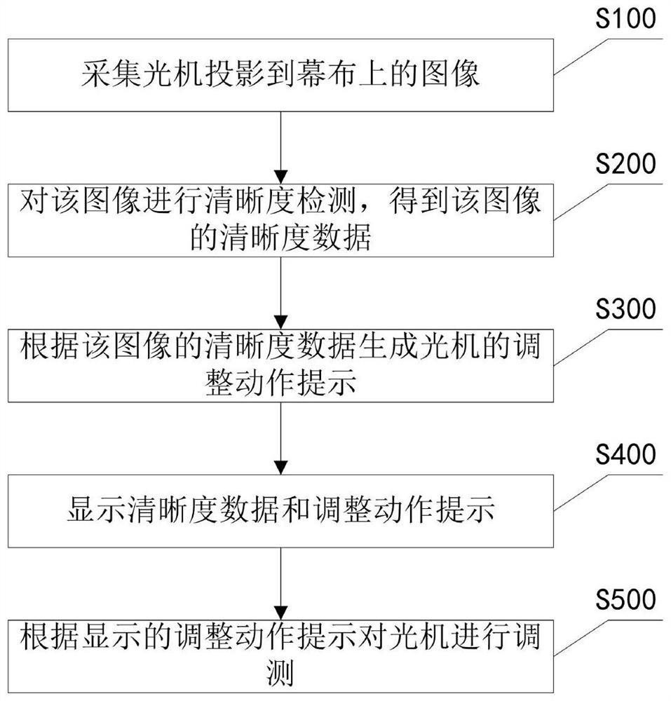
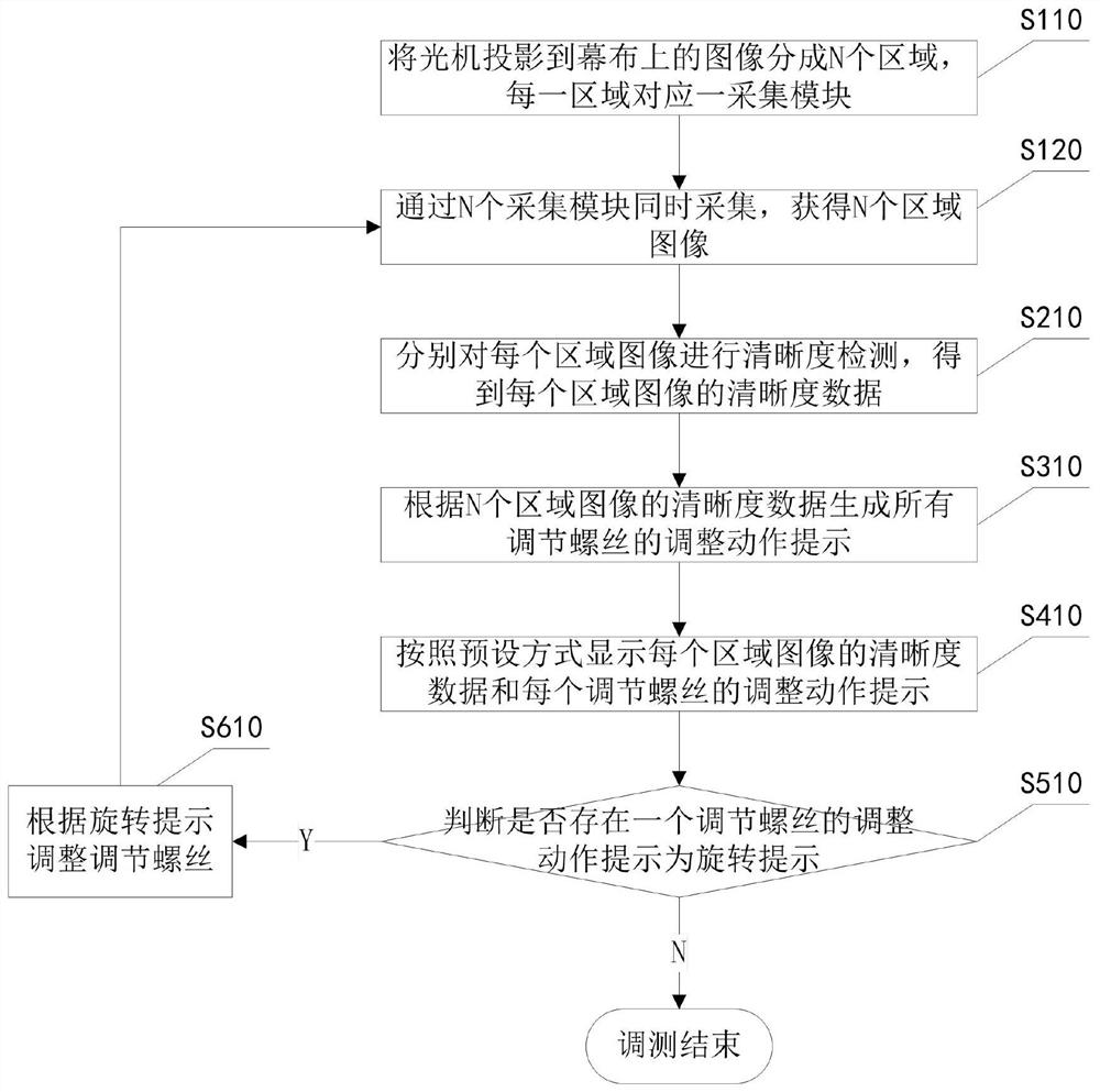
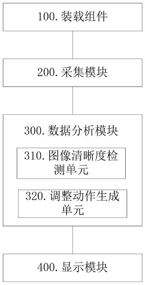
[0032] An embodiment of the invent...


PUM


Abstract

The invention provides an optical machine definition adjusting and measuring method and system. The method comprises the steps: collecting an image projected to a curtain by an optical machine; performing definition detection on the image to obtain definition data of the image; generating an adjustment action prompt of the ray machine according to the definition data; displaying the definition data and the adjustment action prompt; and adjusting and testing the ray machine according to the displayed adjustment action prompt. According to the invention, the debugging and testing efficiency of the definition of the optical machine can be improved, and the requirement on manpower and the omission ratio of products are reduced.

Description

Technical field [0001] The present invention relates to the field of optical machine, especially in an optical machine sharpness, and a system. Background technique [0002] The screen definition to the optimal value to the optimal value and then lock screw fixation. The exhight definition debugging process is quite complicated, and the difference in tiny will cause the sharpness of distinction in a certain area on the screen, causing a blurred phenomenon. [0003] The existing optical sharpness adjustment method is that the person visual projection screen, detects the various regions of the screen, and then adjust the screw on the respective optical axis according to the screen definition and optical machine design according to the screens of each area. Sight adjustment). Its problem is a long time, the loss of poor loss is high, and the intensity of human eye is high, easy to fatigue, and the employer is high. Inventive content [0004] It is an object of the present invention...

Claims


Application Information

Patent Timeline
Patent Type & Authority Applications(China)
IPC IPC(8): H04N17/02
CPCH04N17/02
Inventor 陈细平李志军魏润韬邱柏渝谢晨张师朋胡磊刘建群骆靖
Owner 苏州智瞳道和显示技术有限公司
Why Eureka
Try Eureka