Infrared thermal imaging temperature measuring machine core and thermal imager

A technology of infrared thermal imaging and movement, applied in the field of infrared thermal imaging, can solve the problems of deviation of target temperature value and inability to ensure the accuracy of temperature measurement of thermal imager

Active Publication Date: 2021-10-26
ZHEJIANG DAHUA TECH CO LTD
View PDF7 Cites 2 Cited by
  • Summary
  • Abstract
  • Description
  • Claims
  • Application Information

AI Technical Summary

Problems solved by technology

[0005] The main purpose of the present invention is to provide an infrared thermal imaging temperature measuring core and a thermal imager, to solve the corresponding relationship between the thermal radiation value and the temperature value established by the thermal imaging core in the prior art through the baffle and combine the The target thermal radiation value is used to calculate the actual target temperature value of the target object, resulting in a deviation, which cannot ensure the accuracy of the temperature measurement of the thermal imager

Method used


Image

  • Infrared thermal imaging temperature measuring machine core and thermal imager
  • Infrared thermal imaging temperature measuring machine core and thermal imager
  • Infrared thermal imaging temperature measuring machine core and thermal imager

Examples


Embodiment Construction

[0027] The following will clearly and completely describe the technical solutions in the embodiments of the present invention with reference to the accompanying drawings in the embodiments of the present invention. Obviously, the described embodiments are only some of the embodiments of the present invention, not all of them. The following description of at least one exemplary embodiment is merely illustrative in nature and in no way taken as limiting the invention, its application or uses. Based on the embodiments of the present invention, all other embodiments obtained by persons of ordinary skill in the art without creative efforts fall within the protection scope of the present invention.

[0028] In order to solve the thermal imaging movement in the prior art through the corresponding relationship between the thermal radiation value and the temperature value established by the baffle and combine the target thermal radiation value to calculate the actual target temperature ...


PUM


Abstract

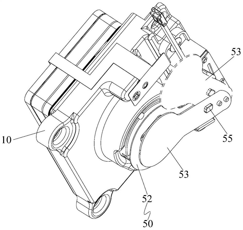
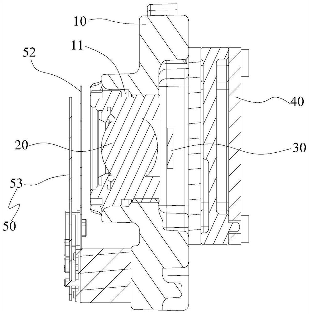
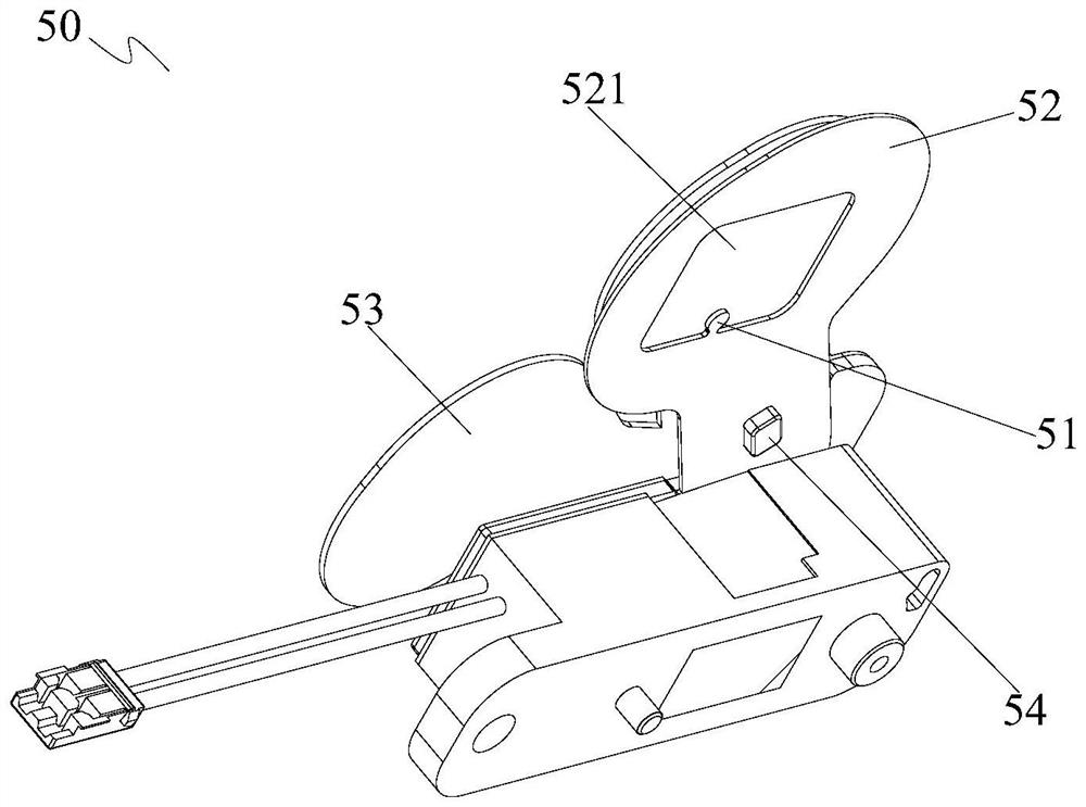
The invention provides an infrared thermal imaging temperature measurement machine core and a thermal imager, the infrared thermal imaging temperature measurement machine core comprises a shell, a lens, a detector, a processor and a separation blade assembly, and the shell is provided with an accommodating cavity and an opening; the lens is arranged in the accommodating cavity and is positioned at the opening; and a blocking sheet assembly, a lens, a detector and a processor are sequentially arranged in the direction from the opening of the shell to the interior of the containing cavity. A calibration lug of the blocking sheet assembly is located in a view field area of the lens to obtain a real-time lug thermal radiation value F1, and the processor obtains a thermal radiation compensation value FB according to the real-time lug thermal radiation value F1 and an actual lug thermal radiation value F4 and corrects a detection target thermal radiation value F2 of the target object through the thermal radiation compensation value FB. According to the invention, the problem that the temperature measurement accuracy of the thermal imager cannot be ensured since the thermal imaging machine core in the prior art generates deviation by calculating the actual target temperature value of the target object through the corresponding relation between the thermal radiation value and the temperature value established by the blocking sheet and combining the target thermal radiation value is solved.

Description

technical field [0001] The invention relates to the technical field of infrared thermal imaging, in particular to an infrared thermal imaging temperature measuring core and a thermal imager. Background technique [0002] Thermal imagers are widely used in social life for human body temperature measurement, biological temperature measurement and industrial temperature measurement through a large-scale, non-contact temperature measurement method. [0003] In the direction from the target object to the thermal imager, the thermal imaging core of the thermal imager sequentially includes a lens, a baffle, a temperature sensor, a detector, and a processor. The baffle is closed so that the baffle is located in the field of view, and the detector acquires The shutter heat radiation value of the shutter, the temperature sensor obtains the shutter temperature value of the shutter, the processor obtains the above-mentioned shutter thermal radiation value and the shutter temperature val...

Claims


Application Information

Patent Timeline
IPC IPC(8): G01J5/00
CPCG01J5/00
Inventor 黄恒敏温跃明卢伍平邱建悦涂应雄
Owner ZHEJIANG DAHUA TECH CO LTD
Why Eureka
Try Eureka