Backlight unit and liquid crystal display employing the same

a backlight unit and liquid crystal display technology, applied in the field of backlight units and liquid crystal displays employing the same, can solve the problems of ccfl being more disadvantageous in instant lighting, comparatively short ccfl being much more disadvantageous in lifetime and color reproducibility, so as to reduce the overall thickness of the system employing, the effect of improving the structur

Inactive Publication Date: 2006-11-23
SAMSUNG ELECTRONICS CO LTD
View PDF11 Cites 84 Cited by
  • Summary
  • Abstract
  • Description
  • Claims
  • Application Information

AI Technical Summary

Benefits of technology

[0016] An apparatus consistent with the present invention relates to a backlight unit having an improved structure such that a heat radiation device is installed inside, decreasing an overall thickness of a system employing the same.

Problems solved by technology

However, the CCFL has a comparatively short lifetime and a low color reproducibility.
The CCFL is much more disadvantageous with respect to lifetime and color reproducibility than a light emitting diode (LED) and is also more disadvantageous in instant lighting than an LED.
Since the CCFL is poor at instant lighting, it is difficult to employ a backlight unit using the CCFL as a light source in a time-division LCD.
The LEDs generate much heat.
However, since the heat radiation fins 5 of the conventional direct light type backlight unit occupy much space, it is difficult to effectively arrange an image board or a power board for an LCD employing the backlight unit.
However, since the conventional direct light type backlight unit fails to prevent light diverging from a selected one of the divided areas from invading an adjacent area, it is difficult to effectively remove the motion blur phenomenon in that an after-image remains when an image frame is changed to another one.

Method used


Image

  • Backlight unit and liquid crystal display employing the same
  • Backlight unit and liquid crystal display employing the same
  • Backlight unit and liquid crystal display employing the same

Examples


Embodiment Construction

[0035] The present invention will now be described more fully with reference to the accompanying drawings, in which exemplary embodiments of the invention are shown.

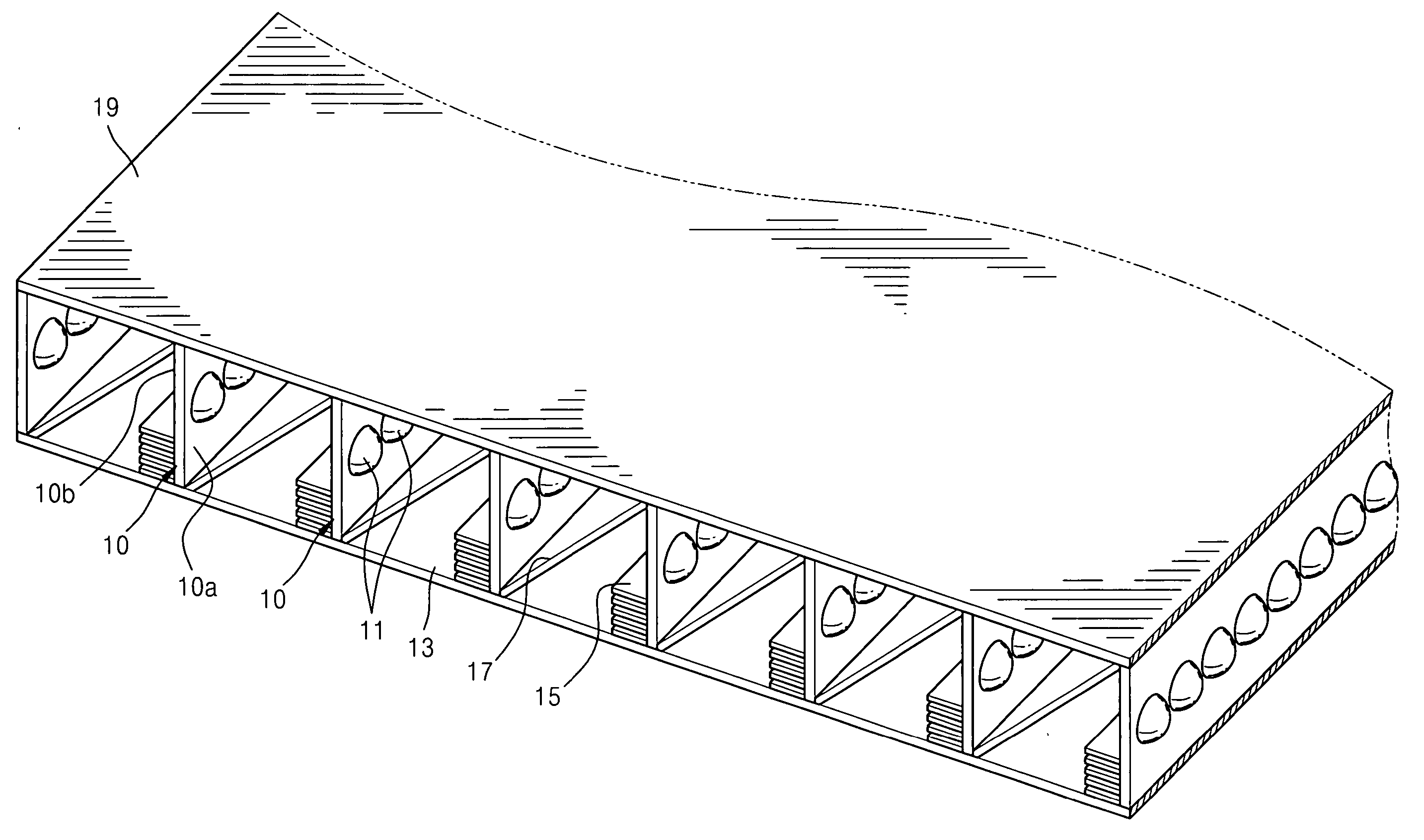
[0036] In a backlight unit according to the present invention, a heat radiation structure is placed inside the backlight unit. Also, the backlight unit has a structure that while being used as a light source for an LCD, the backlight unit has N-number of division areas so as to be sequentially lighted in synchronization with a scanning time of a liquid crystal panel, a light source, for example, an LED, is positioned between barrier ribs defining the division areas, a heat radiation device, for example, a heat radiation fin, is attached on an opposite wall surface of the barrier ribs, and one division area bi-divides light reflection and heat radiation.

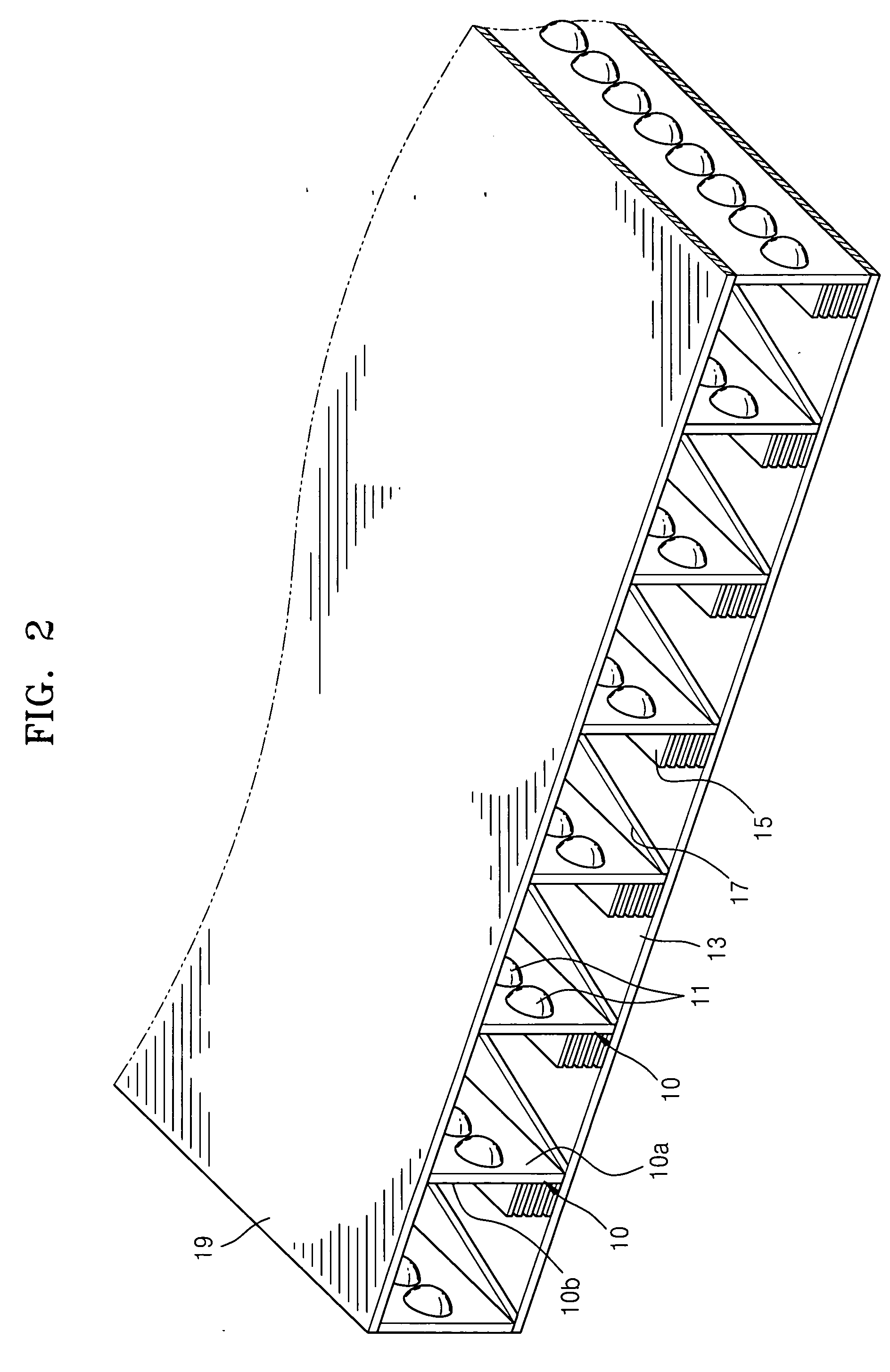
[0037]FIG. 2 is a perspective view partially showing a backlight unit according to an exemplary embodiment of the present invention, and FIG. 3 is a detailed view of a s...


PUM


Abstract

A backlight unit and an LCD employing the backlight unit are provided. The backlight unit includes: a plurality of division areas; a light source which is able to be lighted and is disposed on one sidewall surface of a barrier rib defining the plurality of division areas; and a heat radiation device disposed on an opposite wall surface of the barrier rib to the one sidewall surface, wherein each of the plurality of division areas is constructed to bi-divide light reflection and heat radiation.

Description

CROSS-REFERENCE TO RELATED PATENT APPLICATION [0001] This application claims priority from Korean Patent Application No. 10-2005-0042184, filed on May 19, 2005, in the Korean Intellectual Property Office, the disclosure of which is incorporated herein in its entirety by reference. BACKGROUND OF THE INVENTION [0002] 1. Field of the Invention [0003] The present invention relates to a backlight unit and a liquid crystal display employing the same and, more particularly, to a backlight unit that can perform heat radiation and sequential division lighting, and a liquid crystal display employing the same. [0004] 2. Description of the Related Art [0005] A liquid crystal display (LCD), which is a type of flat panel display, is a light receiving type display that is not self-luminescent but forms an image using incident light from an outside source. A backlight unit is disposed at a rear of the LCD to irradiate light toward a liquid crystal panel. [0006] A cold cathode fluorescence lamp (CCF...

Claims


Application Information

Patent Timeline
Patent Type & Authority Applications(United States)
IPC IPC(8): G09G3/36
CPCG02F1/133603G09G2310/024G09G3/342G02F2001/133628G02F1/133628G02F1/1335
Inventor SEONG, KI-BUMCHO, TAE-HEEWANG, JONG-MINOH, JIN-KYOUNGKIM, SU-GUNJUNG, IL-YONG
Owner SAMSUNG ELECTRONICS CO LTD
Why Eureka
Try Eureka