
Battery temperature controller for electric vehicle using thermoelectric semiconductor

a technology of thermoelectric semiconductors and electric vehicles, applied in cell temperature control, electric devices, electrochemical generators, etc., can solve the problems of low battery performance, delay, high battery energy, etc., and achieve noise and vibration, easy implementation, and optimal performance.

Inactive Publication Date: 2010-05-06
SK INNOVATION CO LTD
View PDF5 Cites 92 Cited by
  • Summary
  • Abstract
  • Description
  • Claims
  • Application Information

AI Technical Summary

Benefits of technology

[0021]The optimal temperature of the batteries is satisfied by automatically control the ON / OFF operation of the thermoelectric semiconductor elements and the direction of current according to conditions of use of the batteries, so that the batteries can realize their optimal performance.
[0022]Furthermore, according to the present invention, semiconductor cooling elements are used as a heat source for cooling and heating, so that noise and vibrations, which are generated by the prior art cooling device using a vehicle air-conditioner or heater or using a fan, can be reduced.
[0023]Furthermore, according to the present invention, the heat radiating operation and the heat absorbing operation can be controlled using a single thermoelectric semiconductor element, so that the temperature control device can be easily implemented.
[0024]Furthermore, according to the present invention, the heat insulating material, which surrounds the batteries, the inlet three-way valve, and the outlet three-way valve isolate the battery unit from the external air, so that the batteries can be protected from variation in the external temperature even when a vehicle is not traveling.
[0025]Furthermore, according to the present invention, the temperature of the battery unit can be more effectively, rapidly and accurately controlled when the temperature of the external air, having a wide temperature range and a large volume, is controlled according to the cooling flow that is formed in order of the heat insulating material, which surrounds the batteries, the inlet three-way valve, the outlet three-way valve and the thermoelectric semiconductor unit.

Problems solved by technology

However, currently, a high battery energy, which is sufficient to operate an electric vehicle, cannot be realized using only a single battery, and thus a plurality of batteries must be connected in series or in parallel not only to realize a high voltage but also to maintain a long lifespan.
When air inside or outside a vehicle is used as described above, a delay occurs until the temperature of the batteries reaches a required appropriate temperature because air outside the vehicle can be anywhere within wide temperature and humidity ranges.
Accordingly, a problem occurs in that the performance of the batteries is lowered until the temperature of the batteries falls within a normal temperature range.
However, the prior art cooling device cannot actively response to variations in the temperature conditions outside a vehicle, that is, low or high temperature conditions.
This is a major cause of reduction in the performance of the batteries.
However, this method not only makes the device complicated but also makes it difficult to control, and thus the manufacturing cost of each vehicle is increased.
However, this method is problematic in that it is difficult to select and use the medium that is used to heat or cool the heat sink and in that a separate heat source must be provided.
In this case, there is a problem in that the heat generated in high-capacity electric vehicle batteries cannot be cooled to an appropriate temperature due to the amount of heat energy that is transmitted to the batteries, depending on the transfer media, and due to a transfer time delay.
Furthermore, the main body casing of each battery is generally made of thick plastic material, rather than metal, so that individual batteries cannot be effectively cooled due to the low thermal conductivity thereof, even if the main body casing is cooled.
In the prior art, there is no cooling device for protecting semiconductor elements from the heat that is generated at the time of reversible reaction of elements, so that a problem occurs in that the elements are overheated and damaged upon practical application.
However, this problem cannot be solved using a method of cooling and heating the outer surface of a battery package.

Method used


Image

  • Battery temperature controller for electric vehicle using thermoelectric semiconductor
  • Battery temperature controller for electric vehicle using thermoelectric semiconductor
  • Battery temperature controller for electric vehicle using thermoelectric semiconductor

Examples


Embodiment Construction

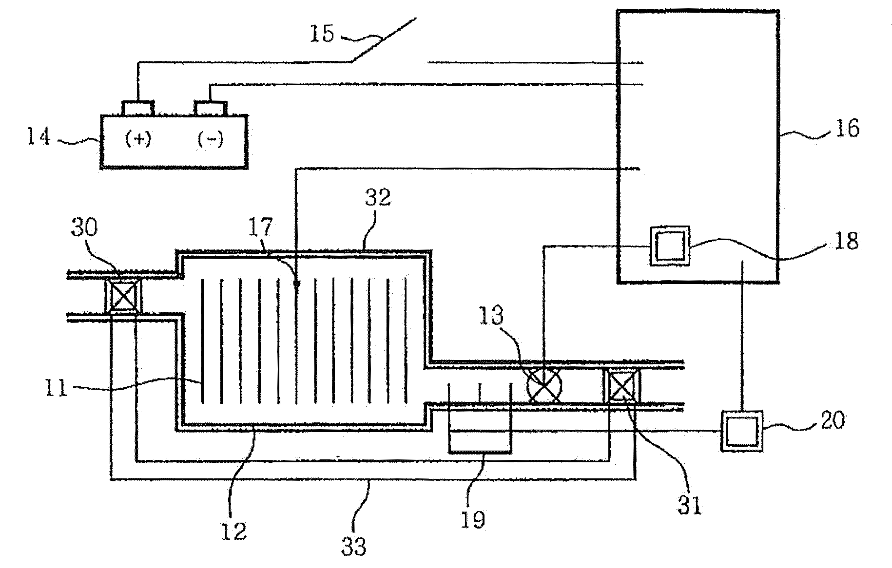
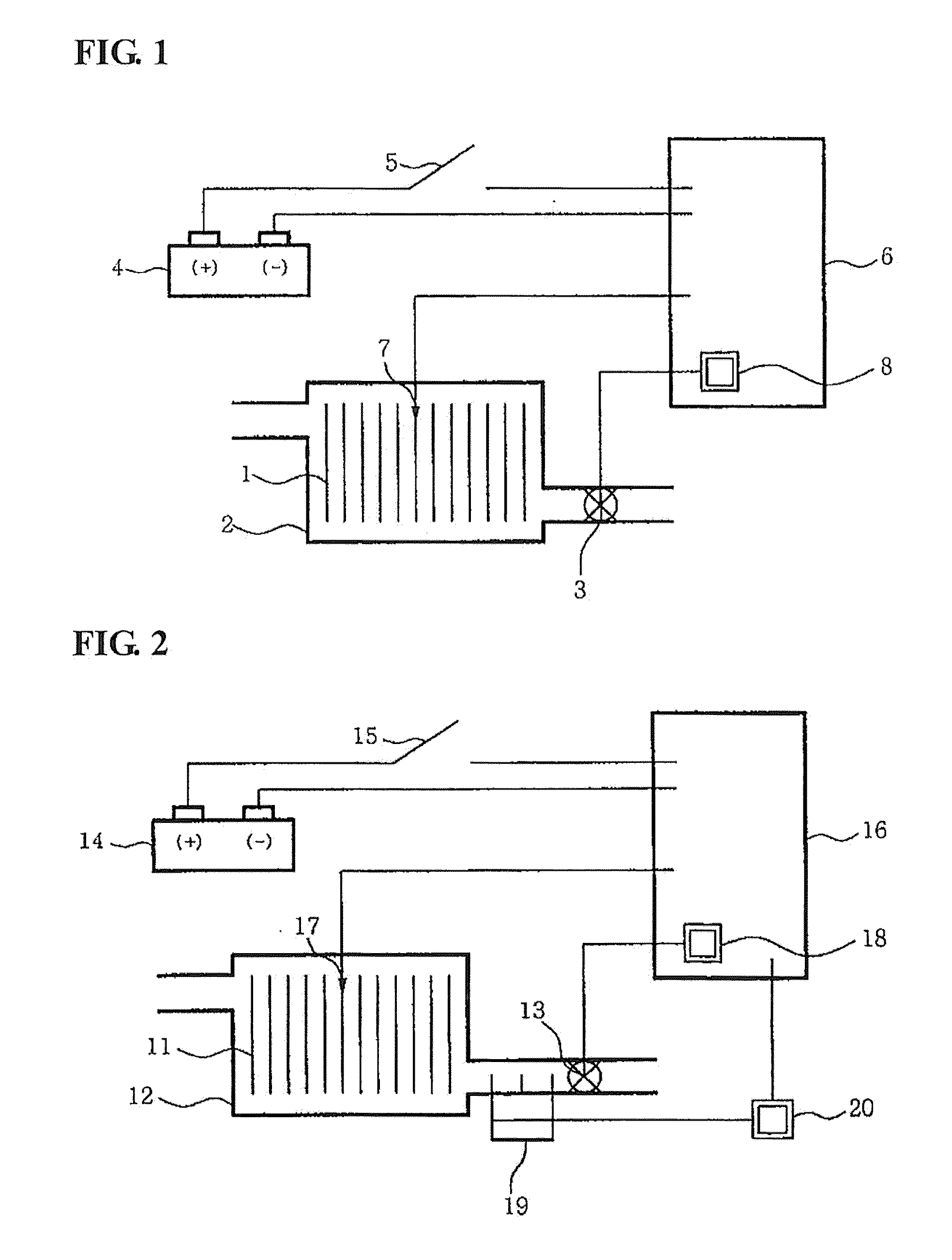
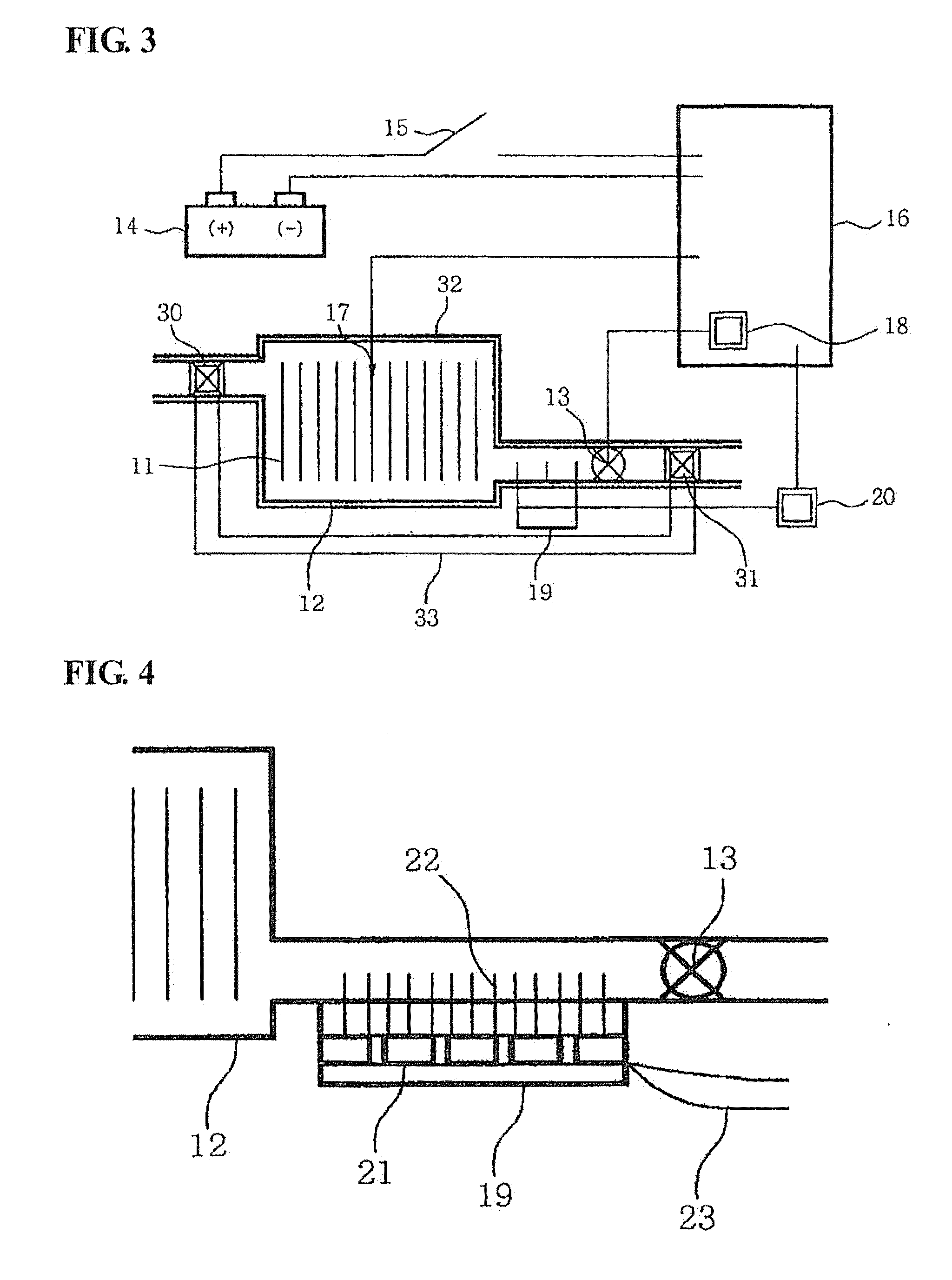
[0054]Meanwhile, a device for controlling the temperature of batteries for electric vehicles using thermoelectric semiconductor elements according to another embodiment of the present invention is described in detail with reference to FIG. 3 below.

[0055]FIG. 3 is a diagram showing the construction of the device for controlling the temperature of batteries for electric vehicles using thermoelectric semiconductor elements according to another embodiment of the present invention.

[0056]Referring to FIG. 3, the device for controlling the temperature of batteries for electric vehicles using thermoelectric semiconductor elements according to the embodiment of the present invention includes a plurality of batteries 11, a battery tray 12, a cooling fan 13, an auxiliary battery 14, a starting switch 15, a battery controller 16, a temperature sensor 17, a relay 18, a thermoelectric semiconductor unit 19, a thermoelectric semiconductor unit controller 20, an inlet three-way valve 30, an outlet ...


PUM


Abstract

Disclosed herein is a device for controlling the temperature of batteries for electric vehicles. The device includes a thermoelectric semiconductor unit, a thermoelectric semiconductor unit, a temperature sensor, and a battery controller. The thermoelectric semiconductor unit is configured such that a portion thereof is exposed in a battery tray. The thermoelectric semiconductor unit controller causes the thermoelectric semiconductor unit to radiate heat, and causes the thermoelectric semiconductor unit to absorb heat. The temperature sensor detects and outputs the temperature of the battery tray. The battery controller outputs the heat radiating control signal to the thermoelectric semiconductor unit controller when the temperature detected by the temperature sensor is lower than a predetermined value, and outputting the heat absorbing control signal to the thermoelectric semiconductor unit controller when the temperature detected by the temperature is equal to or higher than the predetermined value.

Description

TECHNICAL FIELD[0001]The present invention relates to a device for controlling the temperature of batteries for electric vehicles (including hybrid vehicles).[0002]More particularly, the present invention relates to a device for controlling the temperature of batteries for electric vehicles, which can cool batteries, which are mounted in an electric vehicle, using thermoelectric semiconductor elements.BACKGROUND ART[0003]Generally, vehicles are classified into steam vehicles, internal combustion engine vehicles, and electric vehicles according to the type of power source. Of the vehicles, the electric vehicle is currently attracting more attention as a means for solving the problem of serious atmospheric pollution due to the exhaust gas of internal combustion engine vehicles and the problem of increased fuel expenses due to the high price of oil.[0004]Such an electric vehicle is a device that uses electricity as its power source, and is moved by operating an electric motor using ele...

Claims


Application Information

Patent Timeline
IPC IPC(8): H01M10/50
CPCH01M10/482H01M10/486H01M10/625H01M10/63H01M10/615H01M10/6563H01M10/6572H01M10/6566H01M10/613Y02E60/10
Inventor JANG, SOO YEUPLEE, JOONG HUI
Owner SK INNOVATION CO LTD
Learn More