
A fan mesh cover processing device

A processing device and fan net cover technology, applied in cleaning methods and appliances, chemical instruments and methods, cleaning methods using liquids, etc., can solve problems such as difficult cleaning and processing, dead angles, and inability to contact the fan net cover, so as to promote Effects of disengagement, avoidance of obstruction, and avoidance of overheating damage

Active Publication Date: 2021-12-17
南通德惠风机有限公司
View PDF0 Cites 1 Cited by
  • Summary
  • Abstract
  • Description
  • Claims
  • Application Information

AI Technical Summary

Problems solved by technology

[0005] Aiming at the deficiencies of the prior art, the present invention provides a fan net cover processing device, which solves the problem that in the process of washing the existing fan net cover, the net covers are stacked on each other, and dead angles are formed on the surfaces in contact with each other, so that the water flow cannot be connected with the fan net. The problem that it is difficult to realize the cleaning process due to the contact with the mesh cover

Method used


Image

  • A fan mesh cover processing device
  • A fan mesh cover processing device
  • A fan mesh cover processing device

Examples


Embodiment 1

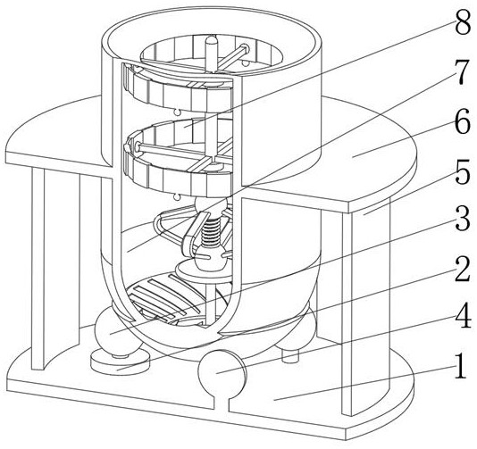
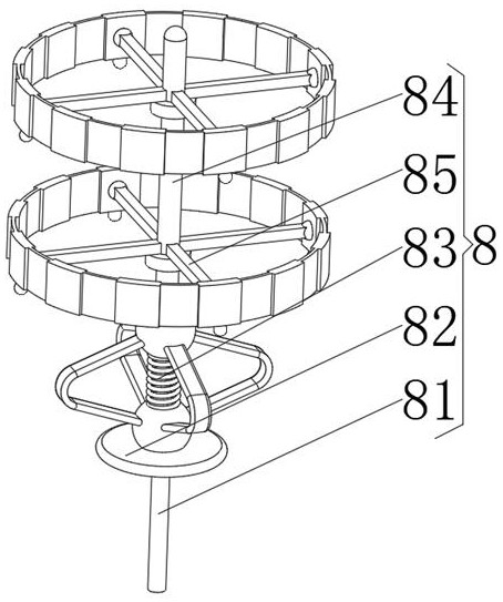
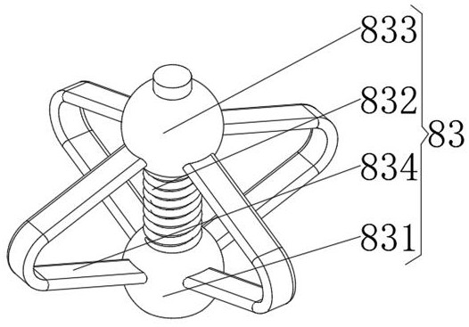
[0037] see Figure 1-5 , the present invention provides a technical solution: a fan net cover processing device, specifically comprising:

[0038]Base plate 1, the base plate 1 has a circular seat plate, and a drive motor 2 installed in the middle of the top of the circular seat plate, and a friction ball 3 installed on the top of the drive motor 2, and the top of the circular seat plate And the support rotating ball 4 that becomes equilateral triangular position with drive motor 2, and the fixed frame 5 that is installed on the top of the circular seat plate and is positioned at the outside of drive motor 2, and the operating panel 6 that is installed on the top of fixed frame 5, and is installed on The processing cylinder 7 at the middle position of the operation panel 6, and the processing device 8 installed at the middle position of the inner cavity bottom of the processing cylinder 7, contact the processing cylinder 7 through the setting of the friction rotating ball 3 an...

Embodiment 2

[0050] see Figure 1-5 On the basis of Embodiment 1, the present invention provides a technical solution: a method for using a fan grille processing device, comprising the following steps,

[0051] Step 1: Place the fan guard on the fixing fork 852, and install the carrying device 85 and the fan guard on the surface of the separating pole 84 as a whole, and fix them;

[0052] Step 2: inject water into the processing cylinder 7 in the equipment, so that the water submerges the fan guard;

[0053] Step 3: Start the driving motor 2 to make the friction ball 3 rotate, and use the friction to drive the rotation loop 72 to rotate, and then make the flow concentrating fan plate 73 rotate;

[0054] Step 4: The flow converging fan plate 73 drives the water flow to rotate to form a vortex water flow, so that the water flow can wash and clean the fan net cover;

[0055] Step 5: The centrifugal force generated by the rotation of the water impacts the weight ball 857, the clamp plate 854...


PUM


Abstract

The invention discloses a fan net cover processing device, which specifically includes: a base plate, a fixing frame installed on the top of the circular seat plate and located on the outer side of the driving motor, and an operation device installed on the top of the fixing frame plate, and a processing cylinder installed in the middle of the operation panel, and a processing device installed in the middle of the inner cavity bottom of the processing cylinder, the processing device includes: a positioning rod, the positioning rod has a cylindrical rod body, and is installed The energy carrying plate at the top of the columnar rod body, the rebound device installed on the top of the energy carrying plate, and the separation pole installed on the side of the rebound device away from the energy carrying plate, and installed on the The invention relates to a bearing device for separating the outer surface of a pole, and the invention relates to the technical field of fans. The internal components are fixed and supported by the design of the positioning rod and the separation column, and the fan grille is suspended in the air, which is convenient for subsequent cleaning and avoids dead corners that cannot be cleaned due to the stacking of grilles.

Description

technical field [0001] The invention relates to the technical field of fans, in particular to a fan net cover processing device. Background technique [0002] The fan is a machine that relies on the input mechanical energy to increase the gas pressure and discharge the gas. It is a driven fluid machine. Cleaning is a method of using solvents to remove dirt on the surface of objects. Transformation, dissolution, and peeling to achieve the effects of degreasing, rust removal and decontamination, the grille needs to be cleaned during the processing of the fan grille. [0003] During the washing process of the existing fan net cover, the net covers are stacked on each other, and dead angles are formed on the surfaces in contact with each other, so that the water flow cannot contact the fan net cover, and it is difficult to realize the cleaning process. Contents of the invention [0004] (1) Solved technical problems [0005] Aiming at the deficiencies of the prior art, the p...

Claims


Application Information

Patent Timeline
Patent Type & Authority Patents(China)
IPC IPC(8): B08B3/10B08B13/00
CPCB08B3/102B08B13/00
Inventor 管勇建
Owner 南通德惠风机有限公司
Learn More