Machining system for chain with firm structure

A processing system and solid technology, applied in the direction of metal chains, etc., can solve the problems of hidden safety hazards, easy disconnection at the interface, high energy consumption, and achieve the effect of ensuring processing quality, consistent cutting length and high production efficiency

Pending Publication Date: 2021-10-29
如皋市淇奥五金制品有限公司
View PDF11 Cites 1 Cited by
  • Summary
  • Abstract
  • Description
  • Claims
  • Application Information

AI Technical Summary

Problems solved by technology

[0003] However, in the prior art, the steel wire is still bent and not straight after being uncoiled, and the steel wire needs to be straightened. The steel wire cannot be effectively fixed during transportation, and it is easy to slip, and the shear length of the steel wire will decrease during shearing. Different, affecting product quality, the space occupied by the shearing device is relatively large, and the space is wasted during the process operation. When multiple mechanisms require external driving force, they are usually driven by different driving mechanisms, which consumes high energy and is produced. The chain is only formed by simple bending, and the interface is not reinforced. When pulling a heavy object, the interface is easy to break and cannot bear a large pulling force, and the untreated interface will stretch outward. Open, there is a safety hazard, it is easy to scratch gloves, clothes and other fabrics during operation, and it is inconvenient to use

Method used


Image

  • Machining system for chain with firm structure
  • Machining system for chain with firm structure
  • Machining system for chain with firm structure

Examples


Embodiment Construction

[0055] The present invention will be described in further detail below in conjunction with the accompanying drawings.

[0056] In order to make the object, technical solution and advantages of the present invention clearer, the present invention will be further described in detail below in conjunction with the accompanying drawings and specific embodiments. The following examples can enable those skilled in the art to understand the present invention more comprehensively, but the present invention is not limited to the scope of the described examples.

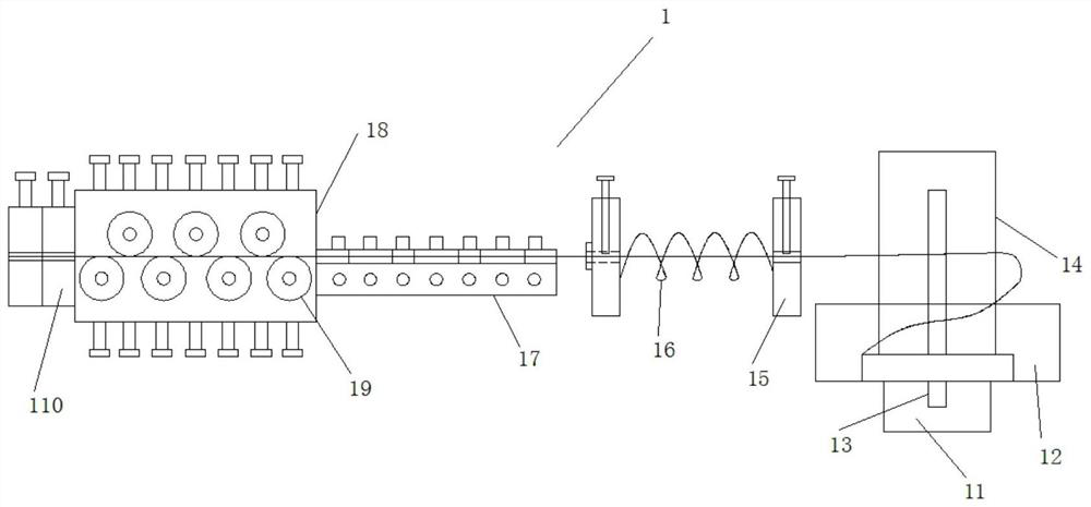
[0057] Such as Figure 1-Figure 10 As shown, this specific embodiment adopts the following technical solutions: including unwinding and straightening device 1, conveying device 2, shearing device 3, bending device 4 and linkage driving device 5, conveying device 2, shearing device 3 and bending The devices 4 are each driven via a linked drive 5 .

[0058] Such as figure 1 As shown, the unwinding and straightening device 1 ha...


PUM


Abstract

The invention discloses a machining system for a chain with a firm structure, and relates to the technical field of chain machining. An unwinding and straightening device is arranged at an input end of a conveying device, a shearing device is arranged at an output end of the conveying device, the shearing device is arranged on one side of a bending device, the conveying device, the shearing device and the bending device are driven by a linkage driving device, an unwinding mechanism drives steel wire coils to rotationally unwind, unwound steel wires enter a straightening mechanism after being guided by a guiding mechanism and then enter a straightening arrangement mechanism from the straightening mechanism, the arranged steel wires are conveyed to the shearing device through a moving seat of the conveying device, and after the shearing device shears the steel wires, the steel wires are bent and machined into the chain through the bending device. The machining system has the advantages that the chain with the firm structure can be machined, fabric cannot be scratched at a connector of the chain, the chain can be effectively fixed during conveying, the shearing lengths of the steel wires are consistent, linkage driving is realized by a plurality of mechanisms, the production efficiency is high, and the production cost is low.

Description

technical field [0001] The invention relates to the technical field of chain processing, in particular to a chain processing system with firm structure. Background technique [0002] Chains are generally metal links or rings, which are mostly used for mechanical transmission, traction, etc., and are also chain-shaped objects that obstruct traffic passages, or are used for hoisting and connection of trailers. The chain is made of steel wire through multiple bending processes. Generally, when processing a chain, it is necessary to unwind the coiled steel wire first, then transport the steel wire to the bending processing area, then cut the steel wire, and finally pass through the bending mechanism. The steel wire is bent to form a chain structure. [0003] However, in the prior art, the steel wire is still bent and not straight after being uncoiled, and the steel wire needs to be straightened. The steel wire cannot be effectively fixed during transportation, and it is easy to...

Claims


Application Information

Patent Timeline
IPC IPC(8): B21F1/00B21F11/00B21F1/02B21F23/00B21L9/00
CPCB21F1/004B21F11/00B21F1/026B21F23/00B21L9/00
Inventor 管永华管彬
Owner 如皋市淇奥五金制品有限公司
Why Eureka
Try Eureka