Rolling type rubber coating machine for self-sealing safety tire rubber sheet and tire rubber coating method of rolling type rubber coating machine

A safety tire and self-sealing technology, which is applied to tires, other household appliances, household appliances, etc., and can solve problems such as film warping on both sides and finale adjustment

Active Publication Date: 2021-10-29
南通骏标自密封安全轮胎科技有限公司
View PDF14 Cites 0 Cited by
  • Summary
  • Abstract
  • Description
  • Claims
  • Application Information

AI Technical Summary

Problems solved by technology

[0004] The purpose of the present invention is to provide a self-sealing safety tire film rolling type rubber coating machine and a tire coating method thereof, to solve the above-mentioned background technology that the pinch cannot be adjusted according to the tire width when pressing and holding, which results in that when the tire width is larger than the pinch There will be a problem that the film on both sides is lifted

Method used


Image

  • Rolling type rubber coating machine for self-sealing safety tire rubber sheet and tire rubber coating method of rolling type rubber coating machine
  • Rolling type rubber coating machine for self-sealing safety tire rubber sheet and tire rubber coating method of rolling type rubber coating machine
  • Rolling type rubber coating machine for self-sealing safety tire rubber sheet and tire rubber coating method of rolling type rubber coating machine

Examples


Embodiment 1

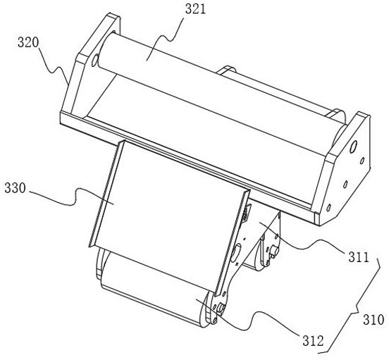
[0050] see figure 1 with figure 2 As shown, the frame body 311 is located on the side of the rubber roll 321 where the rubber layer is placed outside, and a limit plate 330 is provided. The two ends of the limit plate 330 are bent upward to form a limit groove, and the limit plate 330 is close to the finale The side of 312 is inclined, so that the rubber-covered layer is guided to the outside of the pressing shaft 312, so that the final shaft 312 can press the rubber-covered layer on the inner wall of the tire, and the limit groove can limit the rubber-covered layer, so as to solve the problem of the rubber-covered layer in the pressing process. The problem of offset is prone to occur, and the limiting plate 330 and the frame body 311 are fixed by bolts. Before use, install the limiting plate 330 that is suitable for the width of the rubber layer, thereby improving the scope of application of the limiting plate 330.

Embodiment 2

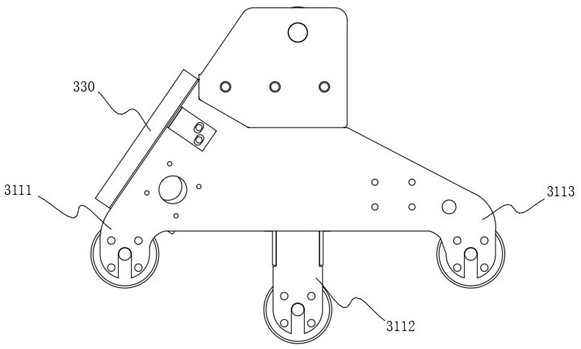
[0052] see image 3 As shown, the frame body 311 includes a driving part 3111 and a recompression part 3113. The driving part 3111 is located on the inclined side of the limit plate 330, and the recompression part 3113 is arranged on the side away from the driving part 3111. The driving part 3111 and the recompression part 3113 The bottoms of the bottoms are all equipped with final shafts 312, and are detachably connected to them, and are specifically fixed by bolts. Before use, replace the final shafts 312 with a length suitable for the width of the rubber layer. The final shafts 312 at the bottom of the driving part 3111 and the repressing part 3113 are both Driven by electric drive equipment, the motor can be used to drive alone, or the two finale shafts 312 can be driven by a motor and a belt at the same time. The latter is preferably used to save power consumption and reduce costs. The finale 312 actively drives the rubber-covered layer to be released, thereby improving t...

Embodiment 3

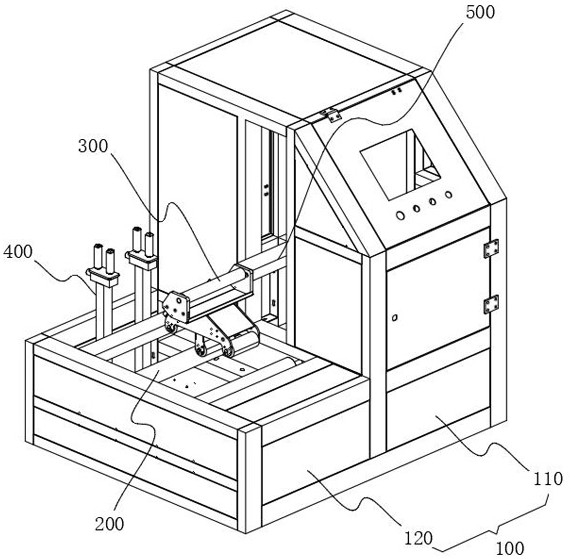
[0055] see Figure 4 As shown, the top of the drive cabinet 120 is also provided with a tire stopper 400, the tire stopper 400 includes a pneumatic flip plate 420, the top of the pneumatic flip plate 420 is rotated along the longitudinal direction and is connected with a plurality of stop bars 430, and the bottom of the pneumatic flip plate 420 is set Bracket 410, the bracket 410 is fixedly connected with the drive cabinet 120 and then supports the pneumatic flip plate 420. When in use, the stop bar 430 is clamped on both sides of the tire to limit the tire and prevent it from tilting, further ensuring that the tire is in the Stability during rotation.

[0056] In addition, the pneumatic turning plate 420 is connected to the bracket 410 through a hinge shaft, and is turned over by pneumatic action, and then the distance between the stop bar 430 and the tire is changed by turning to adapt to the use of tires with different inner diameters.


PUM


Abstract

The invention relates to the technical field of shaft type pressing and covering, in particular to a rolling type rubber coating machine for a self-sealing safety tire rubber sheet and a tire rubber covering method of the rolling type rubber coating machine. The rolling type rubber coating machine comprises a cabinet body, the cabinet body comprises a control cabinet and a driving cabinet arranged at the bottom of one side of the control cabinet, a movable cavity is formed in the top of the driving cabinet, and a movable space is provided for a rubber coating assembly arranged in the movable cavity. The rubber coating assembly specifically comprises a bottom frame and a top frame arranged at the top of the bottom frame, the top of the top frame is rotationally connected with a rubber rolling shaft, a rubber coating layer is wound outside the rubber rolling shaft, the bottom frame comprises a frame body and a pressing shaft arranged outside the frame body, and the pressing shaft is detachably connected with the frame body so as to provide a moving space for the rubber coating assembly arranged in the movable cavity. According to the rolling type rubber coating machine for the self-sealing safety tire rubber sheet and the tire rubber covering method of the rolling type rubber coating machine, the pressing shaft is detachably connected to adapt to the width of the inner wall of a tire, and the stressed area is utilized to the greatest extent when the rubber coating layer is pressed, so that the problem that two sides of the rubber coating layer are likely to tilt after the length of the inner wall of the tire is larger than the length of the pressing shaft is solved.

Description

technical field [0001] The invention relates to the technical field of shaft pressing, in particular to a self-sealing safety tire film rolling type rubber coating machine and a tire coating method thereof. Background technique [0002] Chinese Patent Publication No.: CN106239467A discloses a tire marking device capable of automatic marking, including a base, a mounting plate, a positioning wheel, a positioning wheel clamping adjustment mechanism, a pressure plate, a pressure plate pressure adjustment mechanism, a pen, a pen Positioning mechanism, rotating wheel, motor and control box; the positioning wheel clamping adjustment mechanism is used to adjust the positioning wheel to slide left and right along the long hole of the positioning wheel stroke; the pressure plate compression adjustment mechanism is used to adjust the pressure plate to slide up and down along the pressure plate through hole; stroke positioning The mechanism is used to position and move the stylus; the ...

Claims


Application Information

Patent Timeline
IPC IPC(8): B29D30/06
CPCB29D30/0685B29D2030/0695
Inventor 廖光标廖泽崧廖祎怡郑巧莲
Owner 南通骏标自密封安全轮胎科技有限公司
Why Eureka
Try Eureka