Aerial longitudinal and transverse bullet train

A technology of motor train and lateral drive, applied in the direction of motor vehicles, railway vehicles, trolley cranes, etc., can solve the problems of weak aerial lifting capacity and small service range, and achieve strong lifting capacity, save land, and enhance the ability of anti-risk and disaster relief. Effect

Pending Publication Date: 2021-10-29
李天勇
View PDF2 Cites 0 Cited by
  • Summary
  • Abstract
  • Description
  • Claims
  • Application Information

AI Technical Summary

Problems solved by technology

However, the traditional cableway transportation route is "one" shape, the lifting capacity in the air is weak, and the service range is the area where the "one" shape cableway is located, and the service range is small

Method used


Image

  • Aerial longitudinal and transverse bullet train
  • Aerial longitudinal and transverse bullet train
  • Aerial longitudinal and transverse bullet train

Examples


Embodiment 1

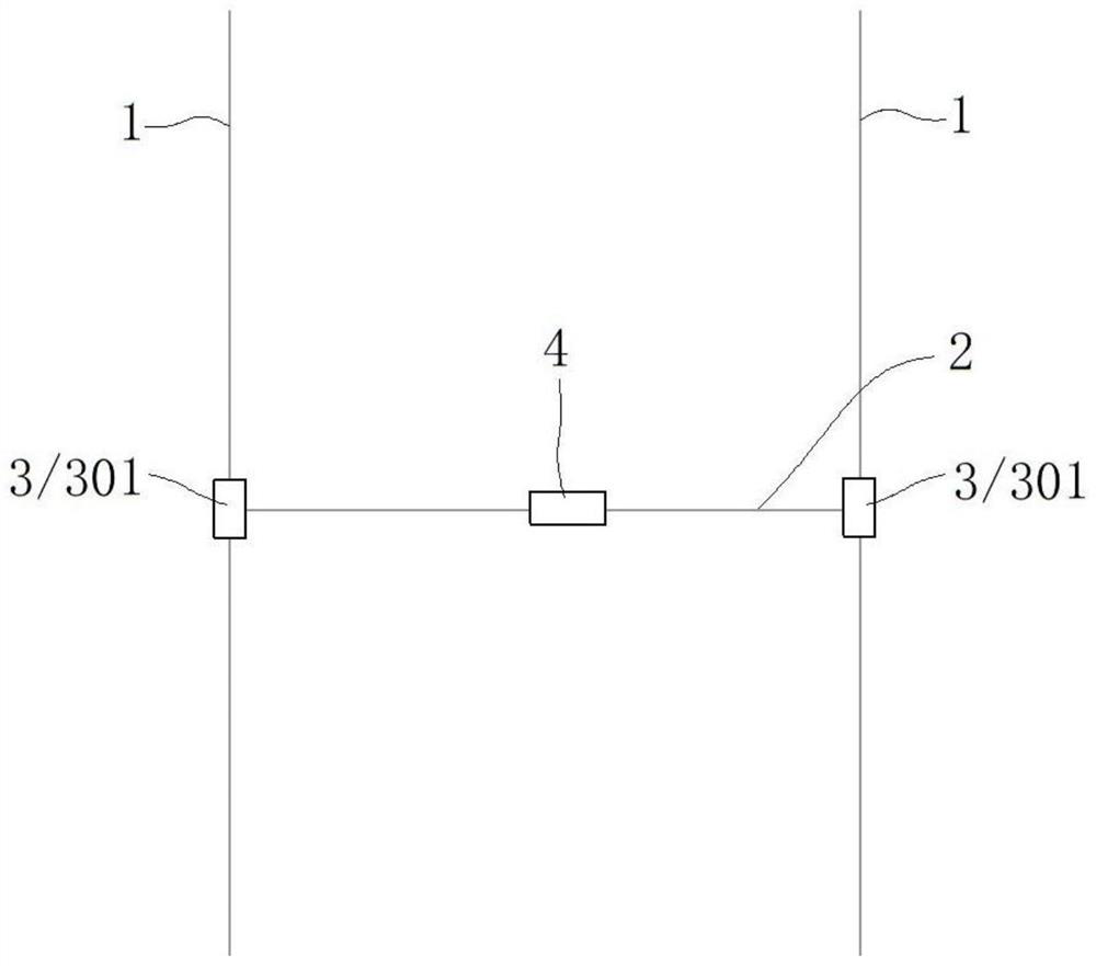
[0051] This embodiment provides a vertical and horizontal moving vehicle in the air, such as figure 1 As shown, in a preferred embodiment, it includes two parallel longitudinal rails 1, a transverse rail 2 arranged across the two longitudinal rails 1, and a longitudinal drive device that drives the transverse rail 2 to run on the longitudinal rail 1 3. And the first motor car 4 that is connected to the transverse track 2 and can run on the transverse track 2 .

[0052] In the present invention, the first motor car 4 is a motor car with a power plant, and the master control room is responsible for issuing a driving instruction. The first motor car 4 can be a single car, or two and more cars; certainly the first motor car 4 can also be a suspension car suspended on the transverse rail 2, similar to a cable car.

[0053] The transverse track 2 of this embodiment runs on the longitudinal track 1 through the longitudinal driving device 3, so that the first moving car 4 moves longi...

Embodiment 2

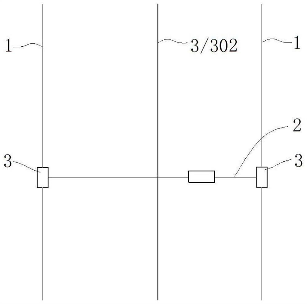
[0066] The structural principle of this embodiment is basically the same as that of the first embodiment, except that the way of driving the transverse track 2 to run on the longitudinal track 1 is different. Such as figure 2 As shown, in this embodiment, regardless of whether the longitudinal rail 1 is horizontal or inclined, the lateral rail 2 is connected with the longitudinal rail 1 and can slide on the longitudinal rail 1. The two ends of the lateral rail 2 are respectively provided with a Set of Scooter Wheels. The longitudinal driving device 3 is a power traction cable 302 connected to the transverse track 2. Under the action of the power traction cable 302, the transverse track 2 runs on the longitudinal track 1 through the sliding wheels to realize the longitudinal movement of the first motor car 4.

Embodiment 3

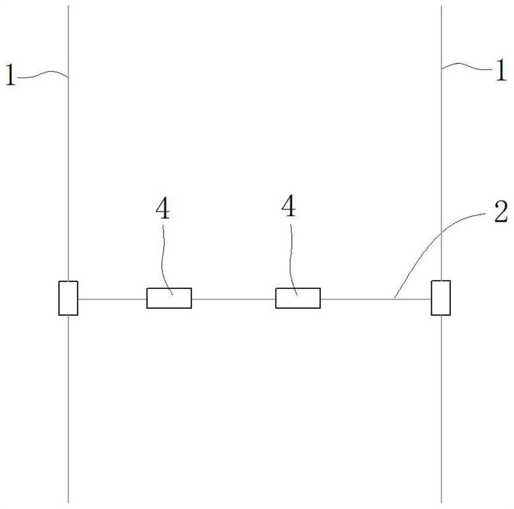
[0068] The structural principle of this embodiment is basically the same as that of Embodiment 1 and Embodiment 2, except that the number of first motor cars 4 arranged on the transverse track 2 is different. Such as image 3 As shown, in this embodiment, the number of first motor cars 4 set on one transverse track 2 is two or more.


PUM


Abstract

The invention provides an aerial longitudinal and transverse bullet train which comprises a plurality of longitudinal rails arranged in parallel, a plurality of transverse rails crossing the longitudinal rails, and a first bullet train body connected with the transverse rails and capable of running on the transverse rails. Each transverse rail is driven by a longitudinal driving device to run on the corresponding longitudinal rail, or each longitudinal rail can longitudinally move in one direction or circularly in a reciprocating mode so that each transverse rail can longitudinally move along with the corresponding longitudinal rail. The rails are vertically and horizontally arranged, the hoisting capacity is high, the span of the rails can be increased to one urban area and even can cover one country, and the service range of the aerial longitudinal and transverse bullet train is large. The urban traffic transportation pressure can be relieved, land is saved, and the bullet train is safer and more environmentally friendly. The bullet train can be widely applied to industries such as military, agriculture, danger resistance and disaster relief, tourism, capital construction, express delivery and the like, and is huge in environmental value and social value.

Description

technical field [0001] The invention belongs to the technical field of air transportation, and in particular relates to an aerial cross train. Background technique [0002] With the development of the economy, the urban population is increasing, and the traffic congestion problem caused by this is also becoming more and more serious. Cableway transportation and aerial rail trains are used by more and more countries due to their small footprint. However, the traditional cableway transportation route is "one"-shaped, and the aerial lifting capacity is weak, and the service range is the area where the "one"-shaped cableway is located, and the service range is small. Contents of the invention [0003] The present invention aims to solve the technical problems existing in the prior art, and the purpose of the present invention is to provide an aerial traversing train. [0004] In order to achieve the above-mentioned purpose, the present invention adopts the following technica...

Claims


Application Information

Patent Timeline
Patent Type & Authority Applications(China)
IPC IPC(8): B61B3/00B61B12/00B65G35/00B66C19/00B66C21/00
CPCB61B3/00B61B12/00B65G35/00B66C19/00B66C21/00
Inventor 李天勇
Owner 李天勇
Why Eureka
Try Eureka