Eureka AIR delivers breakthrough ideas for toughest innovation challenges, trusted by R&D personnel around the world.

Remote anti-electricity-stealing inspection method and device, computer equipment and storage medium

An anti-electricity-stealing and electricity-stealing technology, applied in the field of electric power, can solve the problems of low anti-electricity-stealing positioning efficiency, high computing pressure, and high cost of preventing electricity-stealing, so as to improve the efficiency and accuracy of electricity-stealing prevention, reduce computing pressure, and reduce the cost of electricity-stealing. low cost effect

Pending Publication Date: 2021-10-29
GUANGDONG POWER GRID CO LTD +1
View PDF0 Cites 1 Cited by
  • Summary
  • Abstract
  • Description
  • Claims
  • Application Information

AI Technical Summary

Problems solved by technology

[0003] The purpose of the present invention is to provide a remote anti-stealing inspection method, device, computer equipment and storage media to solve the problem of installing the metering MCU on all electric energy meters in the power system without distinction, and then measure the electric quantity of the electric energy meters in real time. The system will generate a large amount of power data at the same time, so the calculation pressure is high, resulting in low efficiency of anti-theft positioning and high cost of anti-theft technical problems

Method used


Image

  • Remote anti-electricity-stealing inspection method and device, computer equipment and storage medium
  • Remote anti-electricity-stealing inspection method and device, computer equipment and storage medium
  • Remote anti-electricity-stealing inspection method and device, computer equipment and storage medium

Examples


Embodiment 1

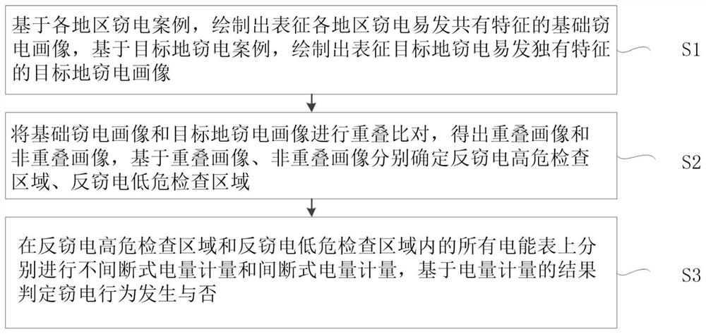
[0029] Such as figure 1 As shown, the present invention provides a kind of remote anti-stealing electricity inspection method, comprises the following steps:

[0030] Step S1. Based on the electricity theft cases in various regions, draw the basic electricity theft portraits representing the common characteristics of electricity theft in each region, and based on the electricity theft cases in the target places, draw the electricity theft portraits in the target places that represent the unique characteristics of the electricity theft in the target places.

[0031] The collection of electricity theft cases in various regions can randomly collect electricity theft cases in various regions of the country, and keep the proportion of electricity theft cases in each region similar, avoiding regional case inclinations, and covering more comprehensive electricity theft common characteristics.

[0032] In step S1, the drawing of the basic electricity stealing portrait specifically inc...

Embodiment 2

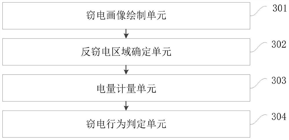
[0078] Such as image 3 As shown, the present invention provides a remote anti-stealing inspection device, which specifically includes the following modules:

[0079] The electricity stealing portrait drawing unit 301 is used to draw a basic electricity stealing portrait representing the common characteristics of electricity stealing in each region based on the electricity stealing cases in each region, and draw a target representing the unique characteristics of electricity stealing in the target region based on the electricity stealing cases in the target region Electricity Stealing Portrait;

[0080] The anti-stealing area determination unit 302 is used to overlap and compare the basic electricity-stealing portrait and the target electricity-stealing portrait to obtain overlapping portraits and non-overlapping portraits, and determine high-risk anti-stealing inspections based on the overlapping portraits and non-overlapping portraits respectively. Areas and anti-stealing l...

Embodiment 3

[0115] Figure 4 A schematic structural diagram of a computer device provided for the implementation of the present invention. Figure 4 A block diagram of an exemplary computer device 13 suitable for implementing embodiments of the invention is shown. Figure 4 The computer device 13 shown is only an example, and should not impose any limitation on the functions and scope of use of the embodiments of the present invention.

[0116] Such as Figure 4As shown, computer device 13 takes the form of a general-purpose computing device. Components of computer device 13 may include, but are not limited to: one or more processors or processing units 16 , system memory 28 , bus 18 connecting various system components including system memory 28 and processing unit 16 .

[0117] Bus 18 represents one or more of several types of bus structures, including a memory bus or memory controller, a peripheral bus, an accelerated graphics port, a processor, or a local bus using any of a variety...


PUM


Abstract

The invention discloses a remote anti-electricity-stealing inspection method and device, computer equipment and a storage medium, and the method comprises the steps: drawing a basic electricity-stealing portrait representing the electricity-stealing common characteristics of each region based on the electricity-stealing cases of each region, and drawing a destination electricity-stealing portrait representing the unique characteristics of the destination electricity-stealing case based on the destination electricity-stealing case; performing overlapping comparison on the basic electricity stealing portrait and the destination electricity stealing portrait to obtain an overlapping portrait and a non-overlapping portrait, and determining an anti-electricity-stealing high-risk inspection area and an anti-electricity-stealing low-risk inspection area based on the overlapping portrait and the non-overlapping portrait respectively; and in the anti-electricity-stealing high-risk inspection area and the anti-electricity-stealing low-risk inspection area, respectively carrying out uninterrupted electric quantity metering and interrupted electric quantity metering on all electric energy meters, and judging whether an electricity stealing behavior occurs or not based on all electric quantity metering results. The cost of the anti-electricity-stealing device is reduced, the operation pressure is small, and the electricity larceny prevention efficiency and precision are improved.

Description

technical field [0001] The invention relates to the field of electric power technology, in particular to a remote anti-stealing inspection method, device, computer equipment and storage medium. Background technique [0002] The existing anti-stealing method is usually to install a metering micro-control unit (Microcontroller Unit; MCU) on each electric energy meter of the power system (to measure the electric quantity of the electric energy meter in real time, and compare the electric energy of the electric energy meter measured in real time with the standard threshold value. Compared, the energy meter that exceeds the standard threshold is determined as the energy meter that steals electricity, and the location of the electricity theft is realized by using the position of the energy meter. Although this method can locate the location of the electricity theft to a certain extent, the metering MCU is in the All electric energy meters in the power system are installed without ...

Claims


Application Information

Patent Timeline
Patent Type & Authority Applications(China)
IPC IPC(8): G06Q30/00G06Q50/06G06K9/62
CPCG06Q30/0185G06Q50/06G06F18/23G06F18/211
Inventor 吴裕宙翁校新冯亮新刘锦宁
Owner GUANGDONG POWER GRID CO LTD
Why Eureka
Eureka Blog
Learn More