
Disc type motor rotor

A disc motor and rotor technology, applied in the manufacture of stator/rotor body, magnetic circuit rotating parts, magnetic circuit shape/style/structure, etc. The effect of preventing stress deformation, preventing dispersion of the magnetic conductive sheet, and improving the fixing effect

Pending Publication Date: 2021-10-29
ZHEJIANG PANGOOD POWER TECH CO LTD
View PDF6 Cites 2 Cited by
  • Summary
  • Abstract
  • Description
  • Claims
  • Application Information

AI Technical Summary

Problems solved by technology

In the switched reluctance motor, it is necessary to use a magnetic block with excellent magnetic permeability to improve its motor performance. At present, the magnetic block formed by stacking sheet-shaped silicon steel sheets has excellent magnetic permeability, but the magnetic block formed by stacking sheet-shaped silicon steel sheets Medium-silicon steel sheets and silicon steel sheets are discrete, making it difficult to carry out industrial production

Method used


Image

  • Disc type motor rotor
  • Disc type motor rotor
  • Disc type motor rotor

Examples


Embodiment Construction

[0055] The following description serves to disclose the present invention to enable those skilled in the art to carry out the present invention. The preferred embodiments described below are only examples, and those skilled in the art can devise other obvious variations. The basic principles of the present invention defined in the following description can be applied to other embodiments, variations, improvements, equivalents and other technical solutions without departing from the spirit and scope of the present invention.

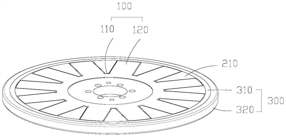
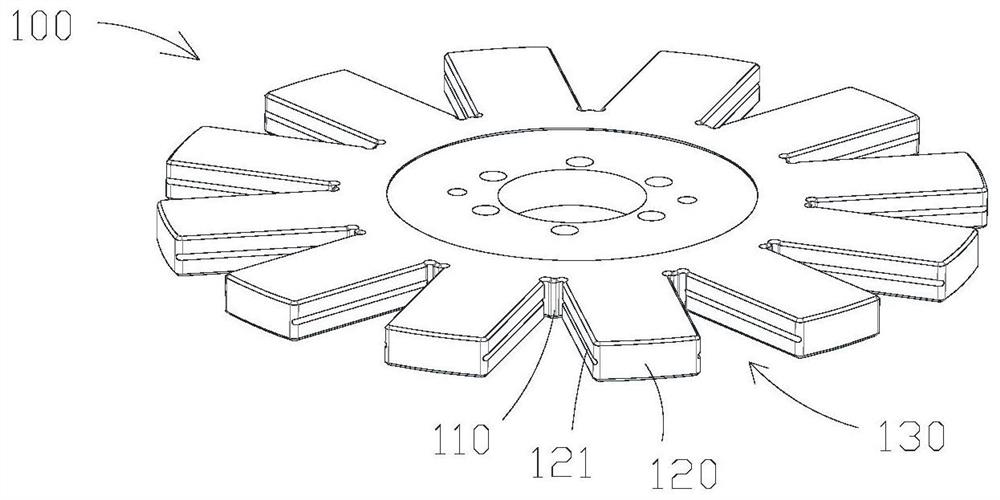
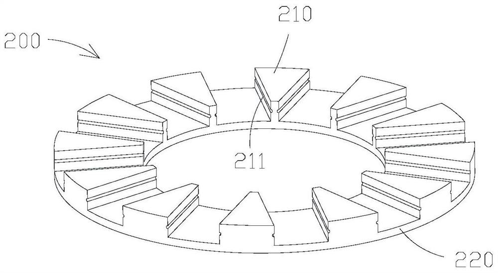
[0056] Such as Figure 1 to Figure 6 As shown, the disc motor rotor includes:

[0057] A non-magnetic cage 100, the non-magnetic cage 100 has a radial limiter 110 and a plurality of circumferential limiters 120, the plurality of circumferential limiters 120 are spaced apart and extend outward connected to the radial limiter 110;

[0058] A magnetically permeable assembly 200, the magnetically permeable assembly 200 has a plurality of magnetically perme...


PUM


Abstract

The invention provides a disc type motor rotor, which comprises a non-magnetic-conductive retainer, a magnetic conducting assembly, a ring assembly and a plurality of axial limiting nails, wherein the non-magnetic-conductive retainer is provided with a radial limiting piece and a plurality of circumferential limiting pieces, and the plurality of circumferential limiting pieces are connected to the radial limiting piece at intervals in an outward extending manner; the magnetic conducting assembly is provided with a plurality of magnetic conducting blocks, each magnetic conducting block is kept between every two adjacent circumferential limiting pieces, and the magnetic conducting blocks abut against the circumferential limiting pieces to form a limiting channel; the ring assembly is arranged on the outer side of the magnetic conducting block in a sleeving mode, and the magnetic conducting block is fixed between the radial limiting piece and the ring assembly in an abutting mode; and each axial limiting nail is kept in one limiting channel, the radial limiting piece and the inner ring are used for fixing the magnetic conducting block in the radial direction, every two adjacent circumferential limiting pieces are used for fixing the magnetic conducting block in the circumferential direction, the axial limiting nails are used for fixing the magnetic conducting block in the axial direction, and the magnetic conducting block is prevented from shaking and falling off.

Description

technical field [0001] The invention relates to the field of disc motors, in particular to a disc motor rotor. Background technique [0002] Motor refers to an electromagnetic device that converts or transmits electric energy according to the law of electromagnetic induction. Its main function is to generate driving torque as a power source for electrical appliances or various machinery. The motor includes a stator and a rotor. The stator is the static part of the electric motor. It is mainly composed of a stator core and a stator winding. The role of the stator is to generate a rotating magnetic field so that the rotor is cut by the magnetic force lines in the magnetic field to generate current. [0003] Among them, motors can be divided into radial field motors and axial field motors. Axial field motors are also called disc motors. They have the characteristics of small size, light weight, short axial dimension and high power density, and can be used in most thin installat...

Claims


Application Information

Patent Timeline
Patent Type & Authority Applications(China)
IPC IPC(8): H02K1/30H02K15/02
CPCH02K1/30H02K15/02
Inventor 孙显旺陈翾
Owner ZHEJIANG PANGOOD POWER TECH CO LTD
Learn More