Detachable motor mounting structure with protection function and mounting method thereof

A protection function and installation structure technology, applied in the field of detachable motor installation structure, can solve the problems of inability to protect the motor, inconvenient maintenance work, difficult disassembly, etc., and achieve the effects of improving maintenance and disassembly efficiency, improving support effect, and increasing friction

Inactive Publication Date: 2021-10-29
李柏万
View PDF1 Cites 0 Cited by
  • Summary
  • Abstract
  • Description
  • Claims
  • Application Information

AI Technical Summary

Problems solved by technology

[0002] Motor refers to an electromagnetic device that realizes the conversion or transmission of electrical energy according to the law of electromagnetic induction, or converts one form of electrical energy into another form of electrical energy. The motor converts electrical energy into mechanical energy, and the generator converts mechanical energy into Electric energy, its main function is to generate driving torque as a power source for electrical appliances or various machinery; therefore, motors are used in many fields, and people often need to fix the motor before using it, because There will be some vibrations when the motor is working, so it is necessary to stabilize the motor, but the motor mounting plate used to fix the motor in the prior art is often fixed to the motor, it is difficult to disassemble for maintenance, and the use of tools is time-consuming and labor-intensive. Inconvenience caused by maintenance work
[0003] After searching, the Chinese patent application number is CN202020332556.1, which discloses a detachable motor mounting plate, including a bottom plate, fixed blocks are fixedly connected to both sides of the top of the bottom plate, and there are fixed blocks inside the fixed block. The top of the bottom plate is provided with a fixed seat, and both sides of the top of the fixed seat are provided with movable slots, but the above technical solution can only fix the base of the motor, so there is still a problem when the motor is working. The mounting plate can only fix the base of the motor, but cannot effectively protect the working motor

Method used


Image

  • Detachable motor mounting structure with protection function and mounting method thereof
  • Detachable motor mounting structure with protection function and mounting method thereof
  • Detachable motor mounting structure with protection function and mounting method thereof

Examples


Embodiment 1

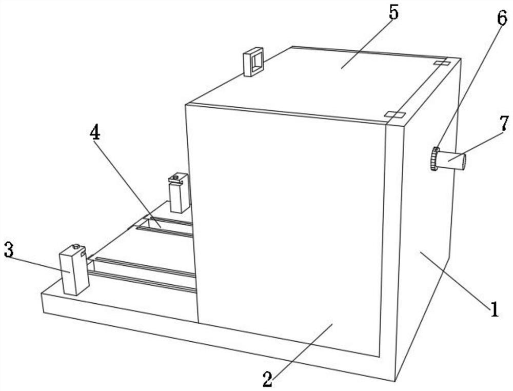
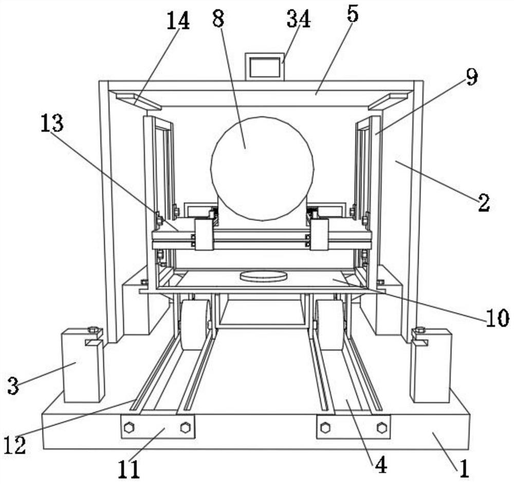
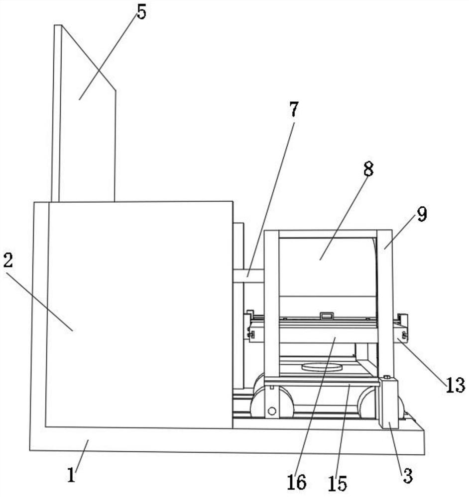
[0043] A detachable motor installation structure with protective function, such as Figure 1-7 As shown, it includes an L-shaped fixed plate 1, the outer wall of one side of the L-shaped fixed plate 1 is provided with two side baffles 2, the top outer wall of the L-shaped fixed plate 1 is fixed with a top cover 5 through a hinge, and the top outer wall of the top cover 5 A second handle 34 is provided, two support blocks 14 are respectively provided on the outer wall of one side of the two side baffles 2, two pulley tracks 4 are arranged on the outer wall of one side of the L-shaped fixed plate 1, and four inner walls of the four pulley tracks 4 are respectively provided with Four rollers 26, four rollers 26 top outer walls are provided with fixed frame 15, fixed frame 15 top outer walls are provided with two support frames 9, two support frames 9 side outer walls are provided with mounting plate 13, and mounting plate 13 top outer walls are provided with There is a motor base...

Embodiment 2

[0054] A method for installing a detachable motor installation structure with a protective function, comprising the following steps:

[0055] S1: first lift the top cover 5 through the second handle 34, and then unscrew the screws used to fix the fixing frame 15 on the two second positioning posts 19;

[0056] S2: pull out the fixing frame 15 by pulling the two supporting frames 9, and then fix the fixing frame 15 on the two first positioning columns 3 by screws;

[0057] S3: move the mounting plate 13 up and down to move the mounting plate 13 to a precise height, and then fix the position of the mounting plate 13 through the first fixing piece 20;

[0058] S4: Place the new motor 8 on the top outer wall of the mounting plate 13, and lift the two pressure plates 31 upward through the two first handles 28 with both hands;

[0059] S5: Both hands push the pressure plate 31 to move left and right through the two first handles 28, when the pressure plate 31 moves to the top of th...


PUM


Abstract

The invention discloses a detachable motor mounting structure with a protection function and a mounting method thereof, relates to the technical field of motor mounting, and aims to solve the problem that a working motor cannot be effectively protected. The structure specifically comprises an L-shaped fixing plate, two side baffles are arranged on the outer wall of one side of the L-shaped fixing plate, and a top cover is fixed to the outer wall of the top of the L-shaped fixing plate through hinges. The mounting method of the motor comprises the steps of firstly, opening the top cover through a second handle, and then screwing off screws, which are used for fixing a fixing frame, on two second positioning columns; and pulling out the fixing frame by pulling two supporting frames. Through the arrangement of pulley rails, first guide sliding grooves and guide plates, rolling of rollers can be guided through the pulley rails, meanwhile, when the fixing frame moves through the rollers, the guide plates can slide in the first guide sliding grooves along with movement of the fixing frame, so that the good supporting and guiding effects on the fixing frame are achieved.

Description

technical field [0001] The invention relates to the technical field of motor installation, in particular to a detachable motor installation structure with protection function and an installation method thereof. Background technique [0002] Motor refers to an electromagnetic device that realizes the conversion or transmission of electrical energy according to the law of electromagnetic induction, or converts one form of electrical energy into another form of electrical energy. The motor converts electrical energy into mechanical energy, and the generator converts mechanical energy into Electric energy, its main function is to generate driving torque as a power source for electrical appliances or various machinery; therefore, motors are used in many fields, and people often need to fix the motor before using it, because There will be some vibrations when the motor is working, so it is necessary to stabilize the motor, but the motor mounting plate used to fix the motor in the ...

Claims


Application Information

Patent Timeline
Patent Type & Authority Applications(China)
IPC IPC(8): H02K5/00H02K5/26
CPCH02K5/00H02K5/26
Inventor 李柏万
Owner 李柏万
Why Eureka
Try Eureka