Paint spraying device for inner wall of ventilating duct

A technology for ventilation pipes and air pipes, which is applied to spray devices, liquid spray devices, paint spray booths, etc., can solve the problems of reduced production efficiency, poor paint uniformity and adhesion, and poor protection of the inner wall of ventilation pipes, and achieves strong heat fluidity. , easy to spray effect

Active Publication Date: 2021-11-02
南通苏瑞冷暖科技发展有限公司
View PDF6 Cites 6 Cited by
  • Summary
  • Abstract
  • Description
  • Claims
  • Application Information

AI Technical Summary

Problems solved by technology

[0003] The existing paint spraying device for the inner wall of the ventilation duct lacks a cleaning mechanism, and it is impossible to clean the dust and rust on the inner wall of the ventilation duct before painting the inner wall of the ventilation duct. The dust and rust will affect the uniformity and adhesion of the sprayed paint, making the sprayed paint The uniformity and adhesion are relatively poor, and the protection of the inner wall of the ventilation duct is poor. In addition, the existing paint spraying device for the inner wall of the ventilation duct lacks a drying mechanism, and the paint cannot be dried while spraying. Most of the paint on the inner wall of the ventilation duct is Naturally air-dried, the drying and solidification efficiency of the paint is low, which reduces the efficiency of production

Method used


Image

  • Paint spraying device for inner wall of ventilating duct
  • Paint spraying device for inner wall of ventilating duct
  • Paint spraying device for inner wall of ventilating duct

Examples


Embodiment Construction

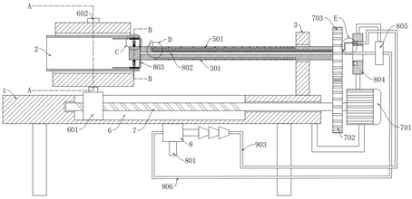
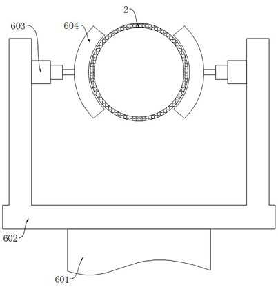
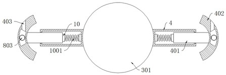
[0025] refer to Figure 1-6 , a painting device for the inner wall of a ventilation duct, comprising a workbench 1 and a ventilation duct 2, the upper end of the workbench 1 is fixedly connected with a vertical rod 3, the side wall of the vertical rod 3 is rotatably connected with a rotating rod 301, and the side wall of the rotating rod 301 is fixedly connected with a spray head 302, a cleaning mechanism is installed on the rotating rod 301, the cleaning mechanism includes two hollow rods 4 symmetrically fixedly connected to the side wall of the rotating rod 301, the inner wall of the hollow rod 4 is slidably connected to a sliding rod 401, and the upper end of the sliding rod 401 is fixedly connected to an arc Scraper 402, arc-shaped scraper 402 is provided with dust suction groove 403, and the side wall of dust suction groove 403 is provided with dust suction hole 404. There is a drying mechanism, the drying mechanism includes an annular groove 5 provided in the rotating ro...


PUM


Abstract

The invention discloses a paint spraying device for the inner wall of a ventilating duct. The device comprises a workbench and the ventilating duct, the upper end of the workbench is fixedly connected with a vertical rod, the side wall of the vertical rod is rotatably connected with a rotating rod, the side wall of the rotating rod is fixedly connected with a nozzle, and the rotating rod is provided with a cleaning mechanism. The cleaning mechanism comprises two hollow rods symmetrically and fixedly connected to the side wall of the rotating rod, the inner walls of the hollow rods are slidably connected with sliding rods, the upper ends of the sliding rods are fixedly connected with arc-shaped scraping plates, dust suction grooves are formed in the arc-shaped scraping plates, dust suction holes are formed in the side walls of the dust suction grooves, and impurity discharging pipes are fixedly connected to the side walls of the arc-shaped scraping plates. Dust and rust on the inner wall of the ventilating duct are scraped away through the arc-shaped scraping plates, cold air generated by a vortex tube can rapidly flow in the dust suction grooves, negative pressure can be generated in the dust suction grooves, then the dust and rust scraped away by the arc-shaped scraping plates are sucked into the dust suction grooves to be discharged, the scraped dust and rust are prevented from falling on the inner wall of the ventilating duct, and the adhesion of the paint is prevented from being affected.

Description

technical field [0001] The invention relates to the technical field of pipe painting, in particular to a painting device for the inner wall of a ventilation pipe. Background technique [0002] Ventilation pipes are metal or composite pipes used in ventilation and air-conditioning engineering of industrial and civil buildings. It is a municipal infrastructure for air circulation and reducing the concentration of harmful gases. Ventilation ducts are painted for protection. [0003] The existing paint spraying device for the inner wall of the ventilation duct lacks a cleaning mechanism, and it is impossible to clean the dust and rust on the inner wall of the ventilation duct before painting the inner wall of the ventilation duct. The dust and rust will affect the uniformity and adhesion of the sprayed paint, making the sprayed paint The uniformity and adhesion are relatively poor, and the protection of the inner wall of the ventilation duct is poor. In addition, the existing p...

Claims


Application Information

Patent Timeline
Patent Type & Authority Applications(China)
IPC IPC(8): B05B16/20B05D3/04B05B13/06B05B9/00B08B9/043B08B13/00
CPCB05B16/20B05D3/0413B05B13/0636B05B9/002B08B9/0436B08B13/00
Inventor 张子文
Owner 南通苏瑞冷暖科技发展有限公司
Why Eureka
Try Eureka