
Thin plate flattening device

A thin plate and extruded plate technology, applied in the field of leveling, to achieve the effects of guaranteed leveling quality, convenient movement, time-saving, labor-saving and high efficiency

Active Publication Date: 2021-11-02
SHANGHAI WAIGAOQIAO SHIP BUILDING CO LTD
View PDF6 Cites 0 Cited by
  • Summary
  • Abstract
  • Description
  • Claims
  • Application Information

AI Technical Summary

Problems solved by technology

[0003]The purpose of the present invention is to overcome the defects of the prior art and provide a thin plate leveling device, which can effectively solve the problem in the background technology that no welding is required when the thin plate is leveled. The efficiency is improved, and the deck will not be deformed for the second time, and the quality of leveling is more guaranteed.

Method used


Image

  • Thin plate flattening device
  • Thin plate flattening device
  • Thin plate flattening device

Examples


Embodiment 1

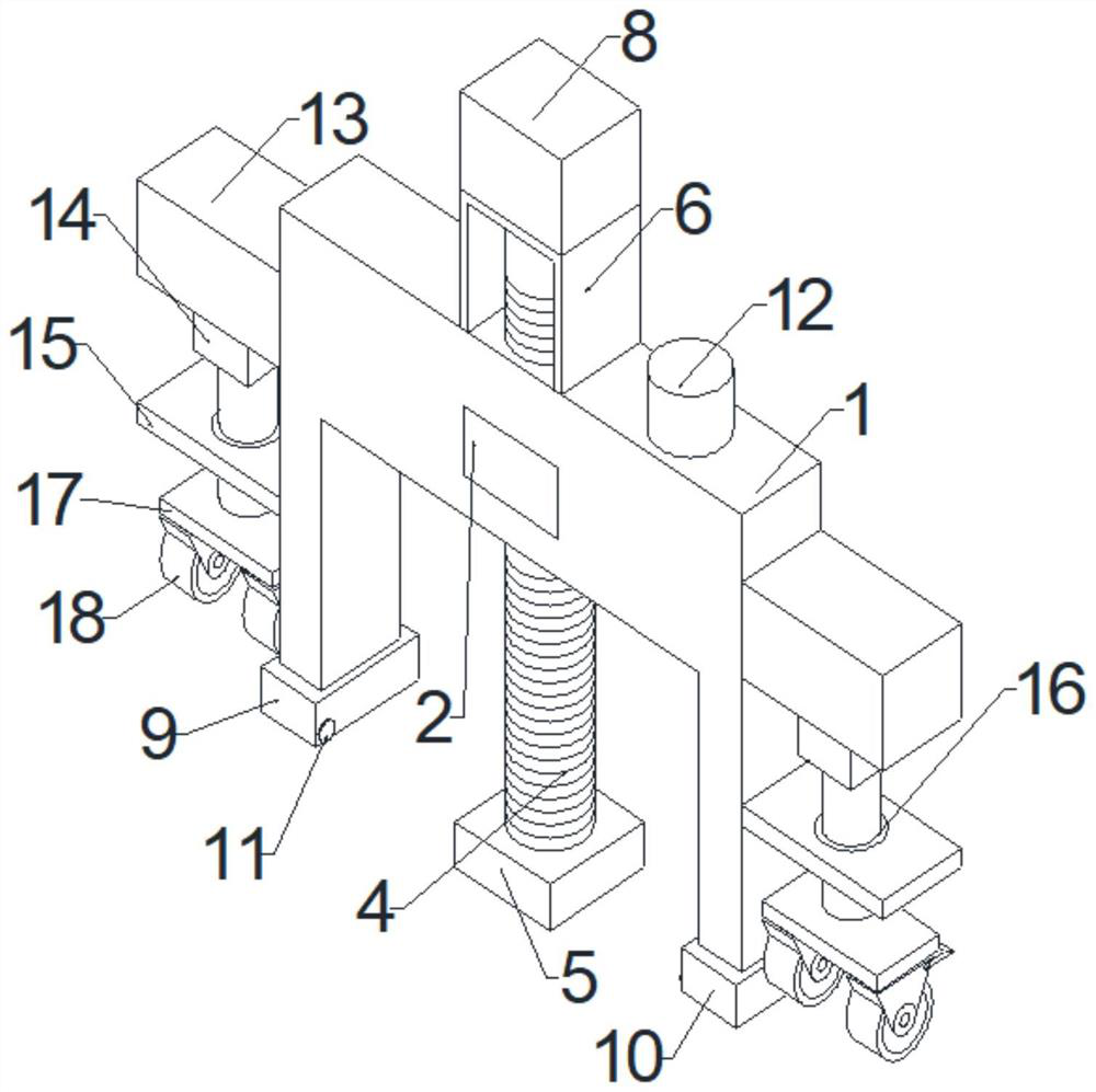
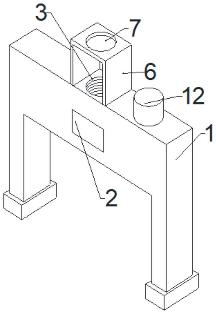
[0030] Such as Figure 1-3 A thin plate leveling device shown includes:

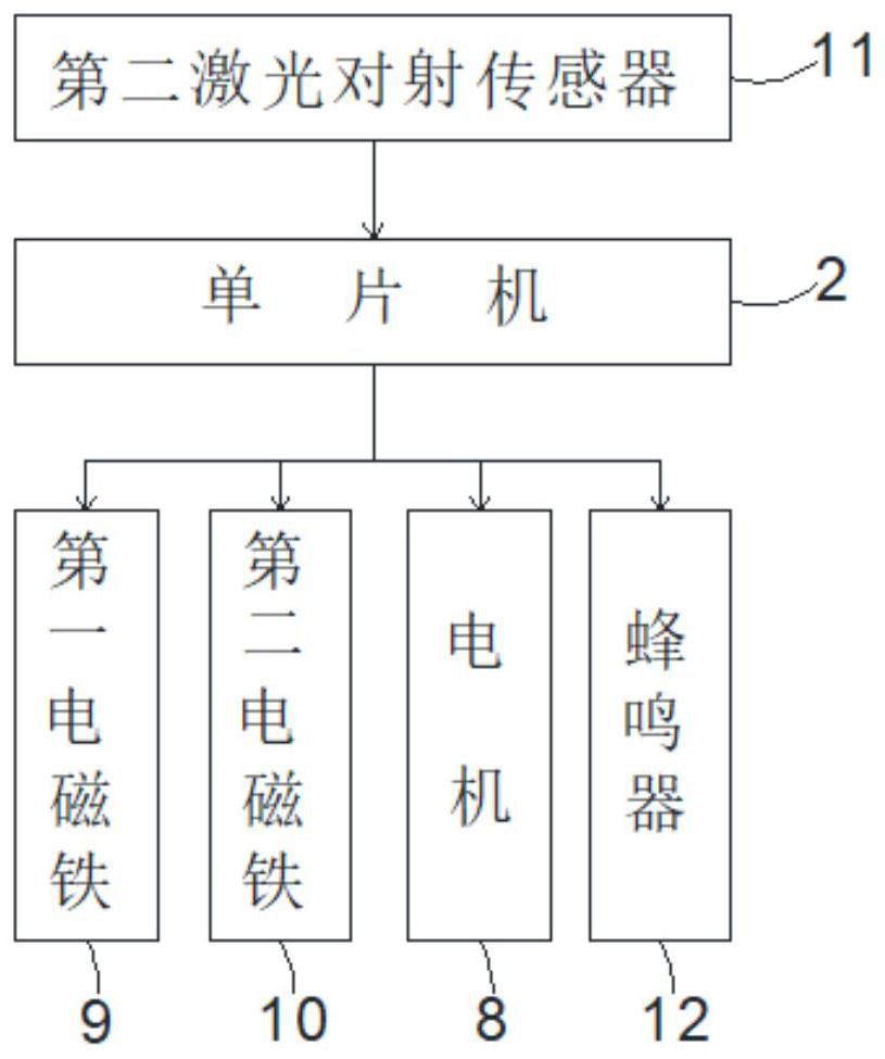
[0031] I-shaped support 1; specifically, the middle part of the I-shaped support 1 is provided with a threaded hole 3 vertically downward; the buzzer 12 is fixed on the described I-shaped support 1; preferred in this embodiment, the The model of the buzzer 12 is KLJ-9032, and when the equipment completes its work, the user will be reminded by the buzzer 12 to increase the use efficiency of the equipment;

[0032] The extruding assembly arranged on the I-shaped support 1; specifically, the extruding assembly includes: threaded rod 4, extruding plate 5, motor fixing seat 6 and motor 8; the extruding plate 5 is fixed on The bottom of the threaded rod 4, the threaded rod 4 is threaded in the threaded hole 3; the motor holder 6 is fixed on the I-shaped support 1, and the motor holder 6 is vertically provided with The first through hole 7; the motor 8 is fixed on the motor holder 6, and the output shaft of t...

Embodiment 2

[0036] refer to Figure 4-6 , further comprising: moving components arranged on the left and right sides of the I-shaped support 1 respectively.

[0037] Specifically, the moving assembly includes: a first fixed part 13, a telescopic cylinder 14, a second fixed part 15, a third fixed part 17 and two roller assemblies 18; the first fixed part 13 and the second fixed part Parts 15 are respectively fixed on the side walls of the I-shaped bracket 1, the second fixing part 15 is directly below the first fixing part 13, and a second fixing part 15 is vertically opened on the second fixing part 15. A through hole 16, the second through hole 16 is provided with a rubber ring 21; the telescopic cylinder 14 is fixed on the bottom of the first fixture 13, and the telescopic end of the telescopic cylinder 14 passes through the rubber ring 21 and Fixed with the third fixture 17; the bottom of the third fixture 17 is fixed with two roller assemblies 18; when the telescopic cylinder 14 work...


PUM


Abstract

The invention discloses a thin plate flattening device. The device comprises an H-shaped support, a control system, an extrusion assembly, a first electromagnet, a second electromagnet and a second laser correlation sensor; the control system is arranged on the H-shaped support; the extrusion assembly is arranged on the H-shaped support; the first electromagnet and the second electromagnet are respectively arranged on two feet at the bottom of the H-shaped support; and the second laser correlation sensor is arranged on the first electromagnet and the second electromagnet. Furthermore, a threaded hole is vertically and downwards formed in the middle of the H-shaped support. Furthermore, the extrusion assembly comprises a threaded rod, an extrusion plate, a motor fixing seat and a motor. According to the thin plate flattening device, by designing the electromagnets to attract and extrude the assembly, welding is not needed, and secondary deformation of the thin plate is avoided, so that the flattening quality of the thin plate is better guaranteed.

Description

technical field [0001] The invention relates to the field of leveling, in particular to a thin plate leveling device. Background technique [0002] Most of the hulls of luxury cruise ships are made of 5-6 mm thin plates. After assembly, electric welding and hoisting, the local deformation will exceed 30 mm. Such a large deformation cannot be leveled without external force. In the past, external force was directly welded on the shelf On the deck surface, use an oil pound to apply external force. The disadvantages of this are that it is more troublesome and inefficient, and the treatment of the welding feet will also cause a second deformation of the deck. Contents of the invention [0003] The object of the present invention is to overcome the defects of the prior art and provide a thin plate leveling device, which can effectively solve the problem in the background technology that when the thin plate is leveled, the efficiency of welding is improved, and the deck will not ...

Claims


Application Information

Patent Timeline
Patent Type & Authority Applications(China)
IPC IPC(8): B21D1/10B21C51/00
CPCB21D1/10B21C51/00
Inventor 方卫民郑志波陈大伟丁尚友陈竹安付直亮吴维淦李壮张杰陈勇雄
Owner SHANGHAI WAIGAOQIAO SHIP BUILDING CO LTD
Learn More