Supercharge Your Innovation With Domain-Expert AI Agents!

Prestress automatic unloading equipment for beam yard

An automatic blanking and prestressing technology, which is applied in the direction of packaging and bundling materials, can solve the problems of easy injury, inaccurate blanking accuracy, and inconvenient cutting, etc., and achieve the goal of improving practicability, firmness, and reliability Effect

Active Publication Date: 2021-11-02
中国建筑土木建设有限公司
View PDF22 Cites 0 Cited by
  • Summary
  • Abstract
  • Description
  • Claims
  • Application Information

AI Technical Summary

Problems solved by technology

The cutting device in the above-mentioned patent has the following disadvantages: although it can meet certain requirements for use, it still has disadvantages such as inaccurate blanking accuracy, inconvenient cutting, and easy injury, so it needs to be improved

Method used


Image

  • Prestress automatic unloading equipment for beam yard
  • Prestress automatic unloading equipment for beam yard
  • Prestress automatic unloading equipment for beam yard

Examples


Embodiment 1

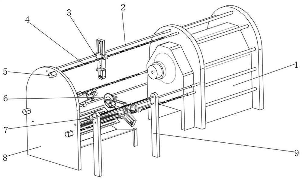
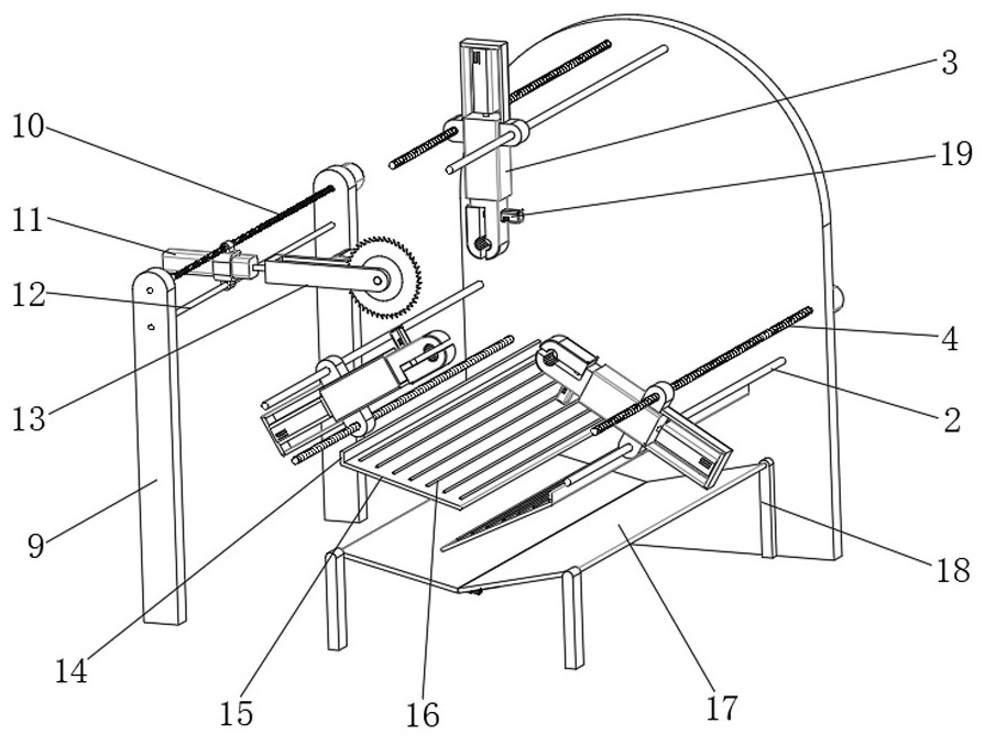
[0036] A kind of prestressed automatic unloading equipment for beam field, such as Figure 1-5 As shown, it includes an equipment main body 1, a cutting mechanism and three clamping mechanisms. One side of the equipment main body 1 is provided with a mounting frame 8, and a first guide rod 2 is fixed between the mounting frame 8 and the equipment main body 1 by screws. The mounting frame 8 One side of the outer wall is fixed with a first translation motor 5 by screws, and the output end of the first translation motor 5 is connected with a first translation screw 4 in rotation. The clamping mechanism includes a first adjustment frame 3, a first clamping part 23 and a second clamp The holding part 22, the first adjusting frame 3 is slidably connected to the outer wall of the first guide rod 2, and the first adjusting frame 3 is connected to the outer wall of the first translation screw 4 through threads, and the top outer wall of the first adjusting frame 3 is fixed with a fixed ...

Embodiment 2

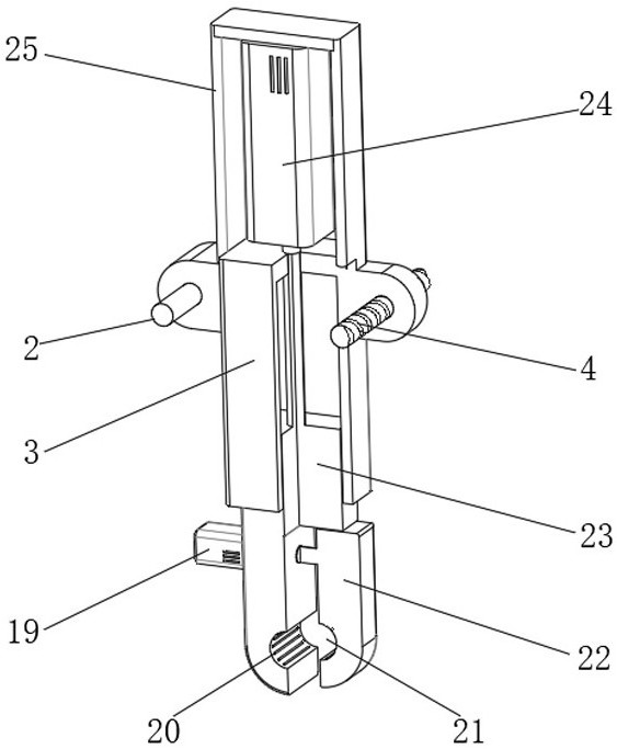
[0046] A kind of prestressed automatic unloading equipment for beam field, such as figure 1 As shown, in order to improve the stability during cutting; this embodiment makes the following improvements on the basis of Embodiment 1: the outer walls of the second clamping part 22 and the first clamping part 23 are provided with a cutting opening 31, and the cutting opening The position of 31 is adapted to the position of cutting wheel 6; by setting structures such as cutting opening 31, when cutting, cutting knife wheel 6 can be sent into cutting opening 31 for cutting, which ensures that the first clamping part 23 of the cutting process The stability of clamping the steel strand by the second clamping portion 22 improves the cutting effect. In the technical solution of the present invention, it is necessary to cooperate with the tying machine to bundle the steel bars. The tying machine is all models or types in the art that can be applied to the prestressed automatic unloading e...


PUM


Abstract

The invention discloses prestressed automatic unloading equipment for a beam yard, and relates to the technical field of unloading equipment for beam yards. In order to improve the cutting effect and efficiency, the equipment specifically comprises an equipment body, a cutting mechanism and three clamping mechanisms, wherein a mounting frame is arranged on one side of the equipment body, a first guide rod is fixed between the mounting frame and the equipment body, a first translation motor is fixed to the outer wall of one side of the mounting frame, and the output end of the first translation motor is rotationally connected with a first translation screw rod; and the clamping mechanism comprises a first adjusting frame, a first clamping part and a second clamping part. By arranging the first adjusting frame, the first clamping part, the second clamping part and other structures, a user can place a to-be-cut steel strand in the equipment body and leads one end of the to-be-cut steel strand out of a containing hole and fixed to the first clamping mechanism. After the first clamping mechanism drags the steel strand to a designated position, the second clamping mechanism fixes the steel strand, and after the two points are firmly fixed, the steel strand is cut by the cutting mechanism.

Description

technical field [0001] The invention relates to the technical field of beam yard unloading equipment, in particular to prestressed automatic unloading equipment for beam yards. Background technique [0002] The prestressed structure is to improve the service performance of the structure. The compressive stress is pre-applied to the structure during the construction period. The prestressed stress during the service of the structure can fully or partially offset the tensile stress caused by the load and avoid structural damage. Parts, such as steel strands Etc. At present, when steel strands are produced and blanked, the manual cutting method is likely to cause inaccurate blanking accuracy, inconvenient cutting, and easy injury, etc., so it needs to be improved. [0003] After searching, the Chinese patent application number is CN201920308108.5, which discloses a cutting device for steel strand processing, including a base, and the outer walls on both sides of the top of the b...

Claims


Application Information

Patent Timeline
Patent Type & Authority Applications(China)
IPC IPC(8): B21F11/00B65B13/02B65B35/12
CPCB21F11/00B65B13/02B65B35/12
Inventor 高树青刘斌包汉营郭志光李星
Owner 中国建筑土木建设有限公司
Features
  • R&D
  • Intellectual Property
  • Life Sciences
  • Materials
  • Tech Scout
  • Unparalleled Data Quality
  • Higher Quality Content
  • 60% Fewer Hallucinations
Learn More