an industrial robot

A technology of industrial robots and swivel seats, which is applied in the field of robots, can solve the problems of reducing the speed of cargo handling, cargo pinch, cargo falling off, etc., and achieve the effect of improving the efficiency of handling, stably clamping the cargo, and stabilizing the clamping force

Active Publication Date: 2022-02-01
ANHUI TECHN COLLEGE OF MECHANICAL & ELECTRICAL ENG
View PDF7 Cites 1 Cited by
  • Summary
  • Abstract
  • Description
  • Claims
  • Application Information

AI Technical Summary

Problems solved by technology

[0002] With the development of industry, a lot of large-scale machinery has appeared. It is difficult to handle manpower and small machinery for handling. Also, when loading and unloading workpieces on the assembly line, manual operation is often used to up and down workpieces. Manual operation has the disadvantage of high labor intensity, so it is necessary When using the mechanical arm, the existing mechanical arm is in use, but during the handling process of the two-point mechanical arm of the industrial robot, due to the uneven road surface or the influence of the weight of the cargo itself, the rotating pair of the clamping part is easy to loosen, and the clamping claw It is difficult to stabilize the clamping force at a suitable clamping force. If the clamping force is too high, the goods will be pinched, and if the clamping force is too small, the goods will fall off. Both situations will affect the goods and cause considerable losses to the enterprise. At the same time, it also reduces the speed of cargo handling. For this reason, we have designed a handling robot arm with firm clamping to solve the above problems.

Method used


Image

  • an industrial robot
  • an industrial robot
  • an industrial robot

Examples


Embodiment 1

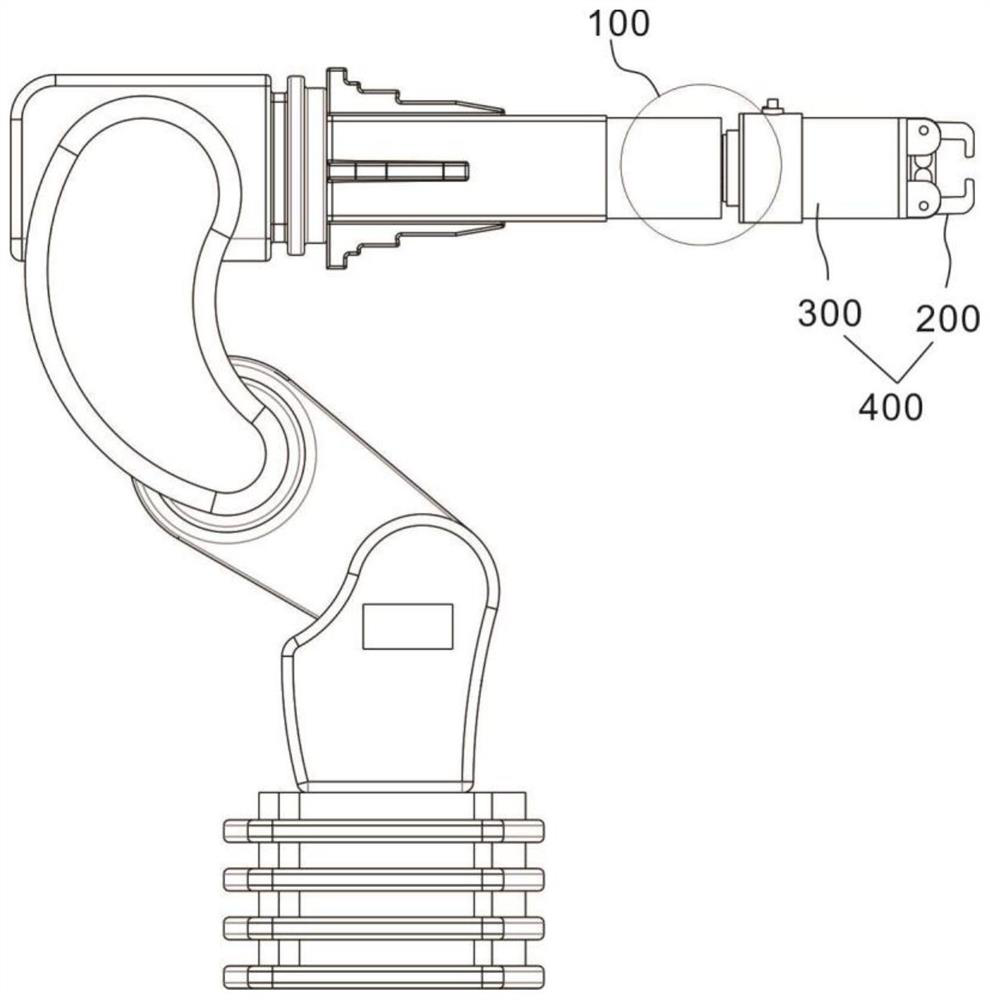
[0035] refer to Figure 1~5 , this embodiment provides an industrial robot, including a rotating unit 100 and a clamping unit 200, wherein the rotating unit 100 provides a rotating pair for the clamping unit, and the clamping unit is used to clamp objects.

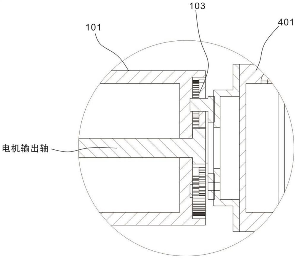
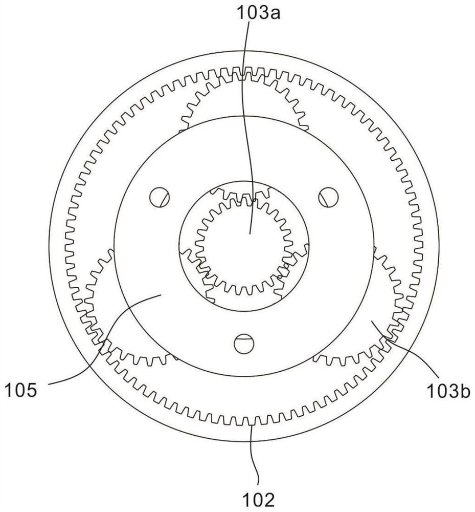
[0036] Specifically, the rotating unit 100 includes a rotating base 101, an internal gear 102 connected to one end of the rotating base 101, and a motor located inside the rotating base 101. The internal gear 102 surrounds the gear ring, and the output shaft of the motor is connected with a gear set 103. The gear set 103 As a reduction gear set, the gear set 103 is connected with a gear frame 104, and the gear frame 104 is connected with a connecting piece 105; the connecting piece 105 is used to connect the gear set 103 with the clamping unit.

[0037] Further, the clamping unit includes a clamping assembly 300 and a control assembly 400 , the control assembly 400 includes a control cylinder 401 , the gear frame 104 is conn...

Embodiment 2

[0043] refer to Figure 1-10 , is the second embodiment of the present invention, this embodiment is based on the previous embodiment, and differs from the previous embodiment in that:

[0044] The clamping assembly 300 is used to clamp the object, and the control assembly 400 is used to control the clamping state of the clamping assembly 300 .

[0045] The clamping assembly 300 includes a fixing plate 301, on which a mounting plate 302 is arranged symmetrically, the mounting plate 302 is arranged perpendicular to the fixing plate 301, a first hole 302a is provided on the mounting plate 302, and a claw 303 is connected to the mounting plate 302 , the claw 303 is C-shaped, the claw 303 is provided with a first shaft 303a, the first shaft 303a is at a bend of the claw 303, the first shaft 303a is embedded in the first hole 302a, the mounting plate 302, the claw 303 are provided with a pair; so the two claws 303 are arranged oppositely, and the ends of the two claws 303 away fro...


PUM


Abstract

The invention discloses an industrial robot, comprising a rotating unit, including a rotating base, an internal gear connected to one end of the rotating base, and a motor located inside the rotating base, the output shaft of the motor is connected with a gear set, and the gear set is connected to There is a gear frame, and the gear frame is connected with a connecting piece; the clamping unit includes a clamping assembly and a control assembly, and the control assembly includes a control cylinder, and the gear frame is connected with the connecting piece; the clamping unit is provided with A rotating pair, so that when clamping objects, the corresponding clamping angle can be adjusted, the clamping force is stable, and the goods being transported will not fall due to unstable clamping force. The position of the clamping arm is mechanically fixed to maintain The clamping strength remains unchanged, which achieves the purpose of stably clamping the goods, and improves the safety and efficiency of goods handling.

Description

technical field [0001] The invention relates to the field of robots, in particular to an industrial robot. Background technique [0002] With the development of industry, a lot of large-scale machinery has appeared. It is difficult to handle manpower and small machinery for handling. Also, when loading and unloading workpieces on the assembly line, manual operation is often used to up and down workpieces. Manual operation has the disadvantage of high labor intensity, so it is necessary When using the mechanical arm, the existing mechanical arm is in use, but during the handling process of the two-point mechanical arm of the industrial robot, due to the uneven road surface or the influence of the weight of the cargo itself, the rotating pair of the clamping part is easy to loosen, and the clamping claw It is difficult to stabilize the clamping force at a suitable clamping force. If the clamping force is too high, the goods will be pinched, and if the clamping force is too sma...

Claims


Application Information

Patent Timeline
Patent Type & Authority Patents(China)
IPC IPC(8): B25J18/00B25J15/00B25J15/08
CPCB25J18/00B25J15/00B25J15/08
Inventor 杨浩
Owner ANHUI TECHN COLLEGE OF MECHANICAL & ELECTRICAL ENG
Why Eureka
Try Eureka