Clamping device for mechanical equipment manufacturing

A kind of equipment and mechanical technology, applied in the field of clamping device structure, can solve the problems of inability to turn over mechanical equipment, poor clamping effect of mechanical equipment, inconvenient processing of mechanical equipment, etc., to achieve convenient processing and manufacturing, good friction effect, and avoid wear and tear Effect

Pending Publication Date: 2021-03-12
唐凯
View PDF8 Cites 0 Cited by
  • Summary
  • Abstract
  • Description
  • Claims
  • Application Information

AI Technical Summary

Problems solved by technology

[0004] The object of the present invention is to provide a clamping device for mechanical equipment manufacturing, to solve the problem that the existing clamping device for mechanical equipment manufacturing proposed in the background technology has a poor clamping effect on mechanical equipment, and the process of clamping and processing In the process, the mechanical equipment cannot be turned over very well, which will make the processing of the mechanical equipment very inconvenient.

Method used


Image

  • Clamping device for mechanical equipment manufacturing
  • Clamping device for mechanical equipment manufacturing
  • Clamping device for mechanical equipment manufacturing

Examples


Embodiment Construction

[0024] The following will clearly and completely describe the technical solutions in the embodiments of the present invention with reference to the accompanying drawings in the embodiments of the present invention. Obviously, the described embodiments are only some, not all, embodiments of the present invention.

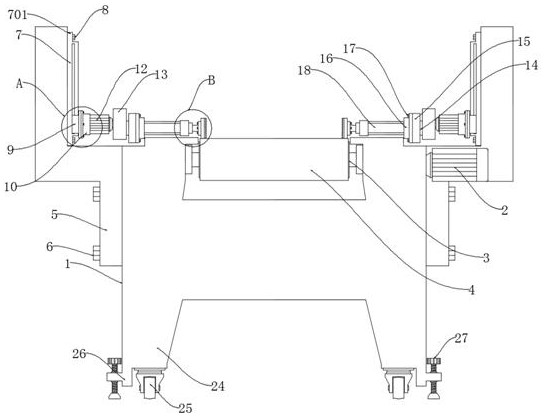
[0025] see Figure 1-5 , an embodiment provided by the present invention: a clamping device for mechanical equipment manufacturing, including a transmission device frame 1, a rotating roller 3 is installed on one side of the inner wall of the transmission device frame 1, and a transmission belt 4 is installed on one end of the rotating roller 3 , both sides of the outer wall of the delivery device frame 1 are equipped with a clamping device mounting frame 5, one side of the upper end of the clamping device mounting frame 5 is equipped with a linear motor 7, and one side of the linear motor 7 is equipped with a moving slide 9, and the moving slide A fixed installation...


PUM


Abstract

The invention discloses a clamping device for mechanical equipment manufacturing, and relates to the technical field of clamping device structures. The clamping device aims to solve the problem that an existing clamping device for mechanical equipment manufacturing cannot well turn over mechanical equipment in the clamping machining process, so that machining of the mechanical equipment is quite inconvenient. Clamping device mounting frames are installed on the two sides of the outer wall of a conveying device frame correspondingly, a linear motor is installed on one side of the upper end of each clamping device mounting frame, a movable sliding base is installed on one side of each linear motor, a fixed mounting box is installed on one side of each movable sliding base, a rotating motor is installed on one side of each fixed mounting box, a transmission device base is installed on one side of each rotating motor, a fixed base is installed on one side of each transmission device base,a connecting base is installed on one side of each fixed base, a clamping air cylinder is installed on one side of each connecting base, a fixed installation plate is installed on one side of each clamping air cylinder, and a clamping plate is installed on one side of each fixed installation plate.

Description

technical field [0001] The invention relates to the technical field of clamping device structure, in particular to a clamping device for manufacturing mechanical equipment. Background technique [0002] There are many types of mechanical equipment, which have become an indispensable mechanical equipment in life and production. When manufacturing mechanical equipment, clamping devices are usually used. Through the clamping device, the mechanical equipment can be used during the manufacturing process. The required parts are clamped, and then the machine is prepared for production and processing by the processing device. [0003] However, the existing clamping device for mechanical equipment manufacturing has a poor clamping effect on the mechanical equipment, and the mechanical equipment cannot be turned over well during the clamping process, which will make the processing of the mechanical equipment very inconvenient. Therefore be badly in need of a kind of clamping device f...

Claims


Application Information

Patent Timeline
Patent Type & Authority Applications(China)
IPC IPC(8): B23Q3/08
CPCB23Q3/08
Inventor 唐凯
Owner 唐凯
Why Eureka
Try Eureka