Multifunctional scraper for oil painting drawing
A multi-functional, scraper technology, applied in painting tools, decorative arts, etc., can solve the problems of inconvenient portability and replacement of oil painting scrapers, and achieve the effect of improving convenience, simple and convenient replacement operation, and convenient use.
- Summary
- Abstract
- Description
- Claims
- Application Information
AI Technical Summary
Problems solved by technology
Method used
Image
Examples
Embodiment 1
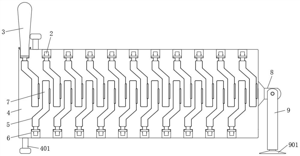
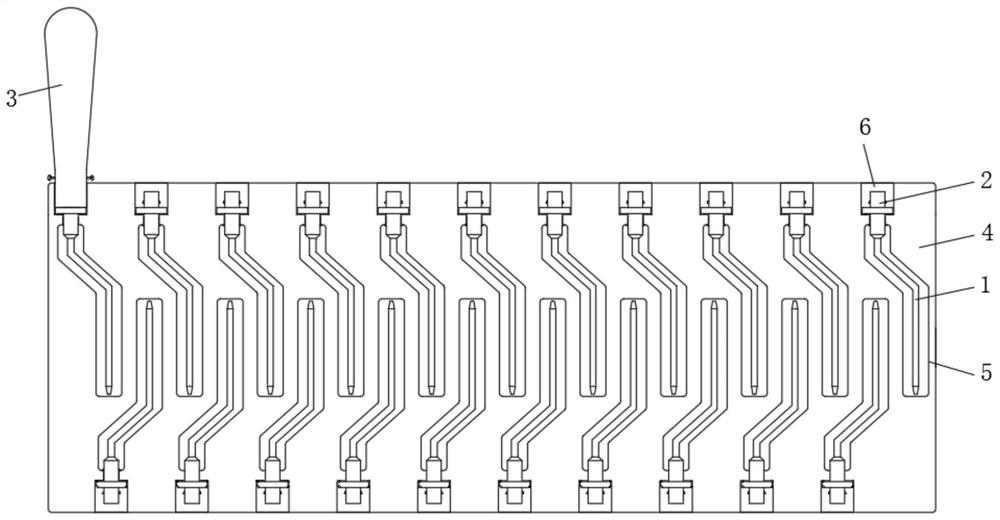
[0033] Embodiment one, by Figure 1 to Figure 7 Given, the present invention includes a scraper body 1, a connection assembly 2, a first handle 3 and a storage plate 4, the connection assembly 2 is connected to the top of the scraper body 1, the first handle 3 is connected to the top of the connection assembly 2, and the storage plate The upper part and the lower part of one side of 4 are equidistantly provided with receiving groove 5, and the top and the bottom of receiving plate 4 are all provided with groove 6, and groove 6 communicates with receiving groove 5, through the setting of receiving groove 5 and groove 6, The scraper body 1 and the connection assembly 2 can be effectively stored, installed and fixed. The connection assembly 2 is movably clamped between the groove 6 and the storage slot 5. The scraper body 1 is located inside the storage slot 5 and one side of the storage slot 5 All are rotated and installed with a sealing baffle 7, through the setting of the seal...
Embodiment 2
[0036] Embodiment two, on the basis of embodiment one, by Figure 4 to Figure 6 Given, the connecting assembly 2 includes a cylindrical connecting bar 201, a coil plate 202, an adjustment cavity 203, a cross turret 204 and two first springs 205, and the cylindrical connecting bar 201 is connected between the scraper body 1 and the first handle 3, And the cylindrical connecting bar 201 is movably clamped between the groove 6 and the receiving groove 5, the coil plate 202 is installed on the upper part of the cylindrical connecting bar 201 and is located inside the groove 6, the adjusting cavity 203 is opened in the middle of the cylindrical connecting bar 201, and the cross The turret 204 is rotatably installed inside the adjustment cavity 203, and the two first springs 205 are connected between the two sides of the upper part of the adjustment cavity 203 and the two sides of the upper part of the cross turret 204, so as to effectively carry out rotation adjustment;
[0037] Tw...
Embodiment 3
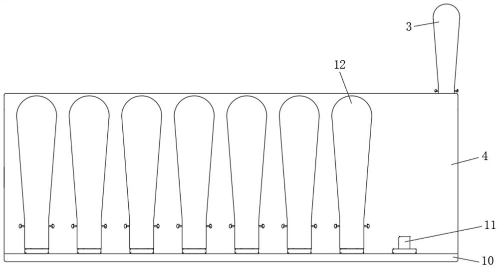
[0042] Embodiment three, on the basis of embodiment one, by Figure 7 It is given that the two sides of the middle part of the convex block 11 are symmetrically provided with clamping holes 1101;
[0043] The bottom of the second handle 12 is provided with a second socket 19, and the bottom of the second handle 12 is symmetrically provided with two second adjusting grooves 20, and the two second adjusting grooves 20 are all communicated with the second socket 19. The insides of each second adjusting groove 20 are all rotatably installed with a second rotation resistance rod 21, and the upper parts of the two second adjusting grooves 20 are equipped with a third spring 22, and one end of the third spring 22 is equipped with a second extruding piece 23. , one side of the second extrusion piece 23 is in contact with one side of the second rotation resistance lever 21, and a second pressing block 24 is installed on the end of the second rotation resistance lever 21 outside the sec...
PUM
 Abstract
Description
Claims
Application Information
 - R&D
- Intellectual Property
- Life Sciences
- Materials
- Tech Scout
- Unparalleled Data Quality
- Higher Quality Content
- 60% Fewer Hallucinations
Browse by: Latest US Patents, China's latest patents, Technical Efficacy Thesaurus, Application Domain, Technology Topic, Popular Technical Reports.
© 2025 PatSnap. All rights reserved.Legal|Privacy policy|Modern Slavery Act Transparency Statement|Sitemap|About US| Contact US: help@patsnap.com


