Method and device for determining state of electropneumatic turnout switch machine

A determination method and technology of switch machines, applied in transportation and packaging, hydraulic equipment for manipulating turnouts or line breakers, railway car body parts, etc., can solve the state detection efficiency of empty turnout switch machine and the accuracy of fault location Low-level problems, to achieve the effect of improving the efficiency of status detection and the accuracy of fault location, improving driving safety, and shortening the duration of status detection

Pending Publication Date: 2021-11-02
中国铁路兰州局集团有限公司 +1
View PDF14 Cites 1 Cited by
  • Summary
  • Abstract
  • Description
  • Claims
  • Application Information

AI Technical Summary

Problems solved by technology

[0005] The present invention provides a method and device for determining the state of an electric-pneumatic turnout switch machine, which are used to solve the problems of low state detection efficiency and fault location accuracy of the electric-pneumatic turnout point machine

Method used


Image

  • Method and device for determining state of electropneumatic turnout switch machine
  • Method and device for determining state of electropneumatic turnout switch machine
  • Method and device for determining state of electropneumatic turnout switch machine

Examples


no. 1 example

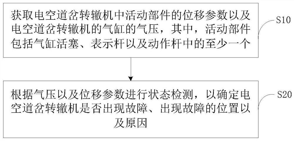
[0071] refer to figure 2 , figure 2 It is the first embodiment of the method for determining the state of the electro-pneumatic switch machine of the present invention, and the method for determining the state of the electro-pneumatic switch machine includes the following steps:

[0072] Step S10, obtaining the displacement parameters of the movable parts in the electropneumatic point switch machine and the air pressure of the cylinder of the electropneumatic point point machine, wherein the movable part includes at least one of a cylinder piston, a display rod and an action rod.

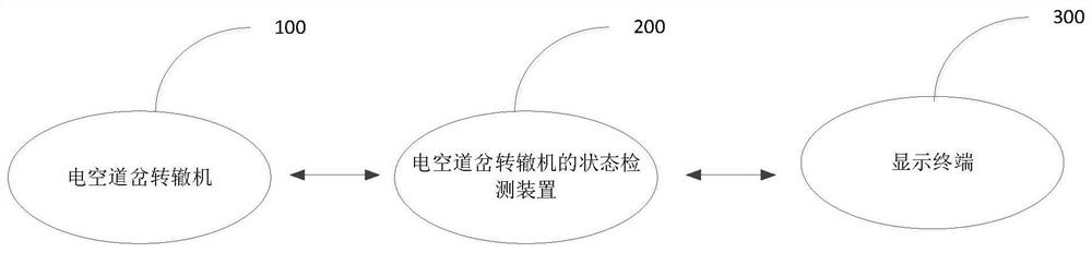
[0073] In this embodiment, the execution subject is a state detection device of an electropneumatic switch machine. For the convenience of description, the device is used below to refer to the state detection device of the electropneumatic switch machine.

[0074] The cylinder in the electro-pneumatic switch point machine is provided with a pressure sensor, which can collect the air pressure in ...

no. 4 example

[0125] refer to Figure 5 , Figure 5 It is the fourth embodiment of the method for determining the state of the electro-pneumatic switch machine of the present invention, based on the third embodiment, step S26 includes:

[0126] Step S261, determine the physical position of the switch and the gap of the switch according to the starting current and the displacement parameters.

[0127] In this embodiment, the current sensor performs sampling according to a preset interval, and the device obtains a starting current sampling sequence based on the currently collected starting current and each historical starting current.

[0128] The starting current is used to control the opening or closing of the positioning electromagnetic pilot valve (reverse electromagnetic pilot valve) of the electropneumatic switch machine. When the control command includes the opening signal of the positioning electromagnetic pilot valve (reverse electromagnetic pilot valve), the positioning electromagn...


PUM


Abstract

The invention provides a method and a device for determining the state of an electropneumatic turnout switch machine. The method comprises the steps: acquiring the displacement parameter of a movable part in the electropneumatic turnout switch machine and the air pressure of an air cylinder of the electropneumatic turnout switch machine, wherein the movable part comprises at least one of an air cylinder piston, an indication rod and an action rod; and performing state detection according to the air pressure and the displacement parameters so as to determine whether the electropneumatic turnout switch machine breaks down or not, the position of the fault and the reason of the fault. According to the method, manual state detection of the electropneumatic turnout switch machine is not needed, the driving safety is improved, the state detection time is greatly shortened, and the state detection efficiency and the fault positioning accuracy of the electropneumatic turnout switch machine are improved.

Description

technical field [0001] The invention relates to the technology of an electropneumatic turnout point machine, in particular to a method and device for determining the state of an electropneumatic turnout point machine. Background technique [0002] Electropneumatic turnout switch machine is an important equipment used in rail transit signaling system. The electric idling turnout machine is controlled by electricity and uses compressed air as the power source. It has the characteristics of fast switching speed, large traction force and reliable locking. [0003] The operation safety of the electric-pneumatic switch machine directly affects the safety of transportation and operation. Therefore, in order to ensure safety, it is necessary to frequently detect the fault location and the cause of the fault during the operation of the electric-pneumatic switch machine. [0004] At present, the commonly used detection methods for electric-pneumatic turnout switch machines are manual...

Claims


Application Information

Patent Timeline
Patent Type & Authority Applications(China)
IPC IPC(8): B61L23/04B61L5/04
CPCB61L23/04B61L5/045
Inventor 李鲲鹏何琦王小卫周晏郭晓龙潘黎鹏姬青杉李兵组李修岭
Owner 中国铁路兰州局集团有限公司
Why Eureka
Try Eureka