Flammable and explosive hazardous chemicals barrier explosion-proof barrel

An explosion-proof, flammable and explosive technology is applied in the field of explosion-proof barrels, which can solve the problems of high risk, increased temperature of oil barrels, aging, etc., and achieve the effect of improving practicability and improving safety.

Active Publication Date: 2022-03-29
中联安全科技(天津)集团股份有限公司
View PDF12 Cites 0 Cited by
  • Summary
  • Abstract
  • Description
  • Claims
  • Application Information

AI Technical Summary

Problems solved by technology

[0002] Oil barrels, that is, barrels used to hold oil, are generally made of iron or plastic in a cylindrical shape. They were originally invented by the Germans on the eve of World War II. They are mainly used to carry important military supplies-gasoline, which can be said to be a typical war product. , before the Second World War, the German Supreme Command formulated the strategy of blitzkrieg, but at the same time there will be a problem, because the offensive speed of each attacking force is too fast, resulting in logistics supplies that cannot keep up. Large tanks, armored vehicles and trucks need a lot of gasoline. The German High Command foresaw this problem and designed a container for gasoline, that is, an oil drum. Great convenience, now a kind of barrier explosion-proof oil storage barrel is needed to achieve better oil storage and make it easier for people to use natural resources. When the existing explosion-proof barrels are in use, because of the hot summer weather, When the amount of oil barrels is large, many oil barrels need to be placed in the sun to expose them to the sun, which will cause the internal temperature of the oil barrels to rise, and the oil body in the oil barrels will also heat up, which will cause the oil body to be poured out for use. , because of the higher temperature, it has a higher risk. At the same time, the climate in summer is changeable, and it often rains after the high temperature. This also causes the oil barrel to withstand temperature changes for a long time, resulting in aging

Method used


Image

  • Flammable and explosive hazardous chemicals barrier explosion-proof barrel
  • Flammable and explosive hazardous chemicals barrier explosion-proof barrel
  • Flammable and explosive hazardous chemicals barrier explosion-proof barrel

Examples


Embodiment 1

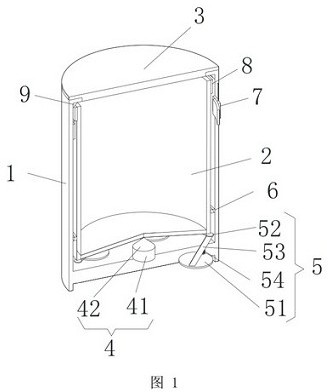
[0033] Example 1: Please refer to figure 1 with Figure 5-6 , inflammable and explosive hazardous chemicals barrier explosion-proof barrel, including outer barrel body 1, the outer barrel body 1 is the barrel body whose upper surface is not completely open, the inner barrel body 2 is arranged in the outer barrel body 1, and the outer barrel body 1 is covered with useful For the sealed barrel cover 3, a supporting device 4 is provided between the outer barrel body 1 and the inner barrel body 2, the bottom surface of the inner barrel body 2 is conical-shaped upwards, and the supporting device 4 corresponds to the raised position of the inner barrel body 2, A stabilizing device 5 is also provided between the outer barrel body 1 and the inner barrel body 2. There are four stabilizing devices 5 located at the bottom of the outer barrel body 1 at equal distances. The stabilizing device 5 includes a chassis 51 and a support plate 52. The positions corresponding to the inner bottom s...

Embodiment 2

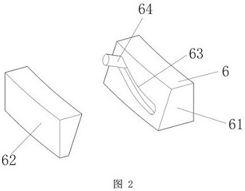
[0036] Embodiment 2: On the basis of Embodiment 1, please refer to figure 2 The force unloading device 6 includes a contact block 61 and a mounting block 62, the contact block 61 and the mounting block 62 are complementary and incomplete circular rings, and both the contact block 61 and the mounting block 62 are blocks with a trapezoidal cross-section. The block 61 is in contact with the inner barrel body 2, and the installation block 62 is fixedly connected with the side wall of the outer barrel body 1. The contact block 61 is provided with a guide chute 63, which is an arc-shaped groove provided obliquely, and guides The upper side of the chute 63 is movably clamped with a connecting column 64, and the position corresponding to the guiding chute 63 on the mounting block 62 is provided with a draw-in slot having the same size as the guiding chute 63, and the other end of the connecting column 64 is connected to the mounting block. 62 are snapped together.

Embodiment 3

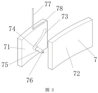
[0037] Embodiment three: on the basis of embodiment two, please refer to Figure 3-4 , the control device 7 includes a fixed plate 71 and a movable plate 72, the fixed plate 71 is an arc-shaped block whose radian is the same as that of the inner wall surface of the outer barrel body 1, and the movable plate 72 is an arc-shaped block whose radian is the same as that of the outer wall surface of the inner barrel body 2 block, the thickness of the fixed plate 71 and the movable plate 72 is adapted to the distance between the outer barrel body 1 and the inner barrel body 2, the size of the movable plate 72 is twice the size of the fixed plate 71, and the fixed plate 71 is close to the movable plate 72 Half of the area on one side of one side fits with the movable plate 72, and the vertical position of the movable plate 72 corresponds to the movable ring 8. The fixed plate 71 is provided with a guide chute 73, and the guide chute 73 is an arc that is inclined. slot, and the guide c...


PUM


Abstract

The invention relates to the technical field of explosion-proof barrels, and discloses a barrier explosion-proof barrel for inflammable and explosive hazardous chemicals, including an outer barrel body, the outer barrel body is a barrel body whose upper surface is not completely open, and an inner barrel body, an outer barrel body, and an outer barrel body are arranged in the outer barrel body. The body is covered with a bung for sealing. A support device is provided between the outer barrel and the inner barrel. The bottom surface of the inner barrel is in the shape of a cone protruding upwards. The support device corresponds to the raised position of the inner barrel. The outer barrel There is also a stabilizing device between the inner barrel and four stabilizing devices located at the bottom of the outer barrel at equal distances. The stabilizing device includes a chassis and a support plate. The disc is in contact with the bottom surface of the inner barrel. The flammable, explosive and hazardous chemicals block the explosion-proof barrel. By using the outer barrel and the inner barrel for split use, it improves the safety and also improves the practicability of the device. .

Description

technical field [0001] The invention relates to the technical field of explosion-proof barrels, in particular to a barrier explosion-proof barrel for inflammable and explosive hazardous chemicals. Background technique [0002] Oil barrels, that is, barrels used to hold oil, are generally made of iron or plastic in a cylindrical shape. They were originally invented by the Germans on the eve of World War II. They are mainly used to carry important military supplies-gasoline. It can be said to be a typical product of war. , before the Second World War, the German Supreme Command formulated the strategy of blitzkrieg, but at the same time there will be a problem, because the offensive speed of each attacking force is too fast, resulting in logistics supplies that cannot keep up. Large tanks, armored vehicles and trucks need a lot of gasoline. The German High Command foresaw this problem and designed a container for gasoline, that is, an oil drum. Great convenience, now a barrie...

Claims


Application Information

Patent Timeline
Patent Type & Authority Patents(China)
IPC IPC(8): B65D8/06B65D25/02B65D81/18B65D81/38B65D53/00
CPCB65D7/22B65D25/02B65D81/18B65D81/3806B65D53/00
Inventor 李锐孟宪玉
Owner 中联安全科技(天津)集团股份有限公司
Why Eureka
Try Eureka