
A pick-and-place device and storage system

A storage system and carrying device technology, applied in the field of storage, can solve the problems of increasing the construction and use cost of the storage system, compressing the storage space of the storage system, and covering a large area of ​​the storage system. The effect of high movement stability

Active Publication Date: 2021-12-28
SANY AUTOMOBILE MFG CO LTD
View PDF0 Cites 1 Cited by
  • Summary
  • Abstract
  • Description
  • Claims
  • Application Information

AI Technical Summary

Problems solved by technology

[0004] In some technologies, a forklift is used as a pick-and-place device. Because there is a counterweight mechanism at the rear end, and a steering space needs to be reserved at the same time, it is bulky and compresses the storage space of the storage system. The storage system occupies a large area and is difficult to construct and use. High cost; in some technologies, four-way shuttle vehicles and other transport vehicles are used as pick-and-place devices, which need to set up horizontal tracks for four-way shuttle vehicles and other transport vehicles in each storage location of the storage system, and for The overall improvement of the lifting channel of the four-way shuttle vehicle and other moving vehicles, especially in heavy-duty handling, a large number of horizontal tracks and lifting channels will compress the storage space of the storage system and increase the cost of construction and use; The technical scheme of carrying two-way shuttle vehicles as a pick-and-place device, due to the large size and long mechanism of the stacker, the flexibility of transfer in the three-dimensional warehouse is poor, which will also compress the storage space of the storage system and improve the construction and use of the storage system cost

Method used


Image

  • A pick-and-place device and storage system
  • A pick-and-place device and storage system
  • A pick-and-place device and storage system

Examples


Embodiment Construction

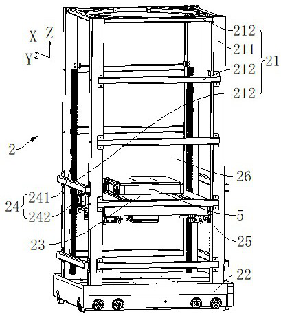
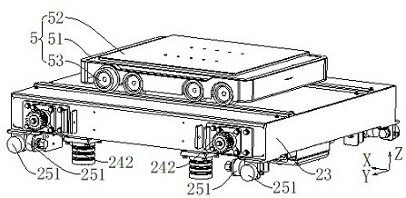
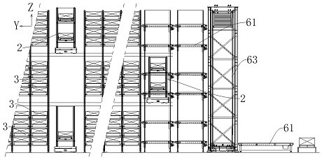
[0037] In order to make the above objects, features and advantages of the present invention more comprehensible, specific embodiments of the present invention will be described in detail below in conjunction with the accompanying drawings.

[0038]In the drawings, the Z-axis represents the vertical direction, that is, the up-down position, and the positive direction of the Z-axis (that is, the arrow pointing to the Z-axis) represents the upward direction, and the negative direction of the Z-axis (that is, the direction opposite to the positive direction of the Z-axis) Indicates down; in the attached figure, the X-axis represents the horizontal direction, and is designated as the left and right positions, and the positive direction of the X-axis (that is, the arrow pointing to the X-axis) represents the right side, and the negative direction of the X-axis (that is, the positive direction of the X-axis In the opposite direction) means the left side; in the attached figure, the Y ...


PUM


Abstract

The invention provides a pick-and-place device and a storage system. The pick-and-place device includes a carrying device and a sub-shuttle. The carrying device includes a carrying frame, a four-way shuttle, a carrying seat, a drive assembly and a guide assembly; the bottom of the carrying frame is connected to the four-way shuttle; the carrying frame includes at least four carrying Each bearing column is arranged at intervals and together forms accommodating space for the bearing seat; a guide assembly is arranged between the bearing seat and the bearing column, and the bearing seat is used to realize the support for the sub-shuttle car, and the sub-shuttle car is used for Lift the cargo unit from below and transfer the cargo unit inside and outside the bearing seat; the drive assembly includes a second rack, a second gear, and a driving member that is drivingly connected to the second gear, and at least one load column is provided with a second rack, The bearing seat is provided with a second gear which meshes correspondingly with the second rack. The pick-and-place device has compact structure, four-way transfer capability, strong carrying capacity, and high motion stability, which can reduce costs and improve operating efficiency.

Description

technical field [0001] The invention relates to the technical field of warehousing, in particular to a pick-and-place device and a warehousing system. Background technique [0002] The storage system can realize the storage of materials and meet the sorting needs, and has broad application prospects in the logistics industry and intelligent manufacturing. [0003] The storage system generally includes three-dimensional shelves and pick-and-place devices. Three-dimensional shelves are generally set up as a multi-layer structure, each layer is provided with a warehouse location, and goods that can be moved in and out are set in the warehouse location. The pick-and-place device transports the goods from a preset location (such as a sorting area) to a storage location, or transports the goods to the preset location after taking them out of the storage location. Therefore, the pick-and-place device is a core of the storage system, and because of the demand for pick-and-place, t...

Claims


Application Information

Patent Timeline
Patent Type & Authority Patents(China)
IPC IPC(8): B65G1/04
CPCB65G1/0492
Inventor 饶有福易小刚师裕强
Owner SANY AUTOMOBILE MFG CO LTD
Learn More