Direct drinking water purification and supply system with self-cleaning function
A water supply system and self-cleaning technology, applied in the directions of cleaning hollow objects, cleaning methods and utensils, heating water/sewage treatment, etc., can solve the problems of increased production cost, high cost, large soaking in acetic acid, etc., and can solve the problem of increasing production cost. Effect
- Summary
- Abstract
- Description
- Claims
- Application Information
AI Technical Summary
Problems solved by technology
Method used
Image

Examples
Embodiment 1
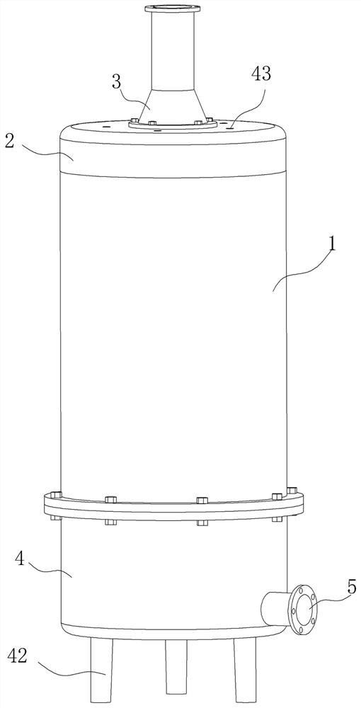
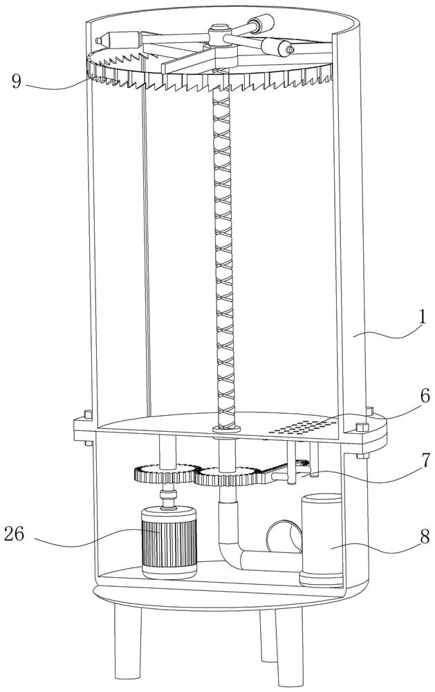
[0027] Example 1: See figure 1 with figure 2 Illustrate embodiment 1, a kind of direct drinking water purification water supply system with self-cleaning function in the figure, comprises reaction kettle 1, spray assembly 8 and cleaning assembly 9, and the top of reaction kettle 1 is connected with top cover 2, and top cover 2 The top of the reaction kettle 1 is connected with a feed pipe 3, and the bottom end of the reaction kettle 1 is fixedly connected with a liquid storage tank 4. The through hole 6, the bottom end of the through hole 6 is equipped with a sealing assembly 7, the spray assembly 8 for spraying the inner wall of the reaction kettle 1 is installed in the liquid storage tank 4, and extends into the reaction kettle 1 for The cleaning assembly 9 that cleans the inner wall of the reactor 1 is installed in the reactor 1;
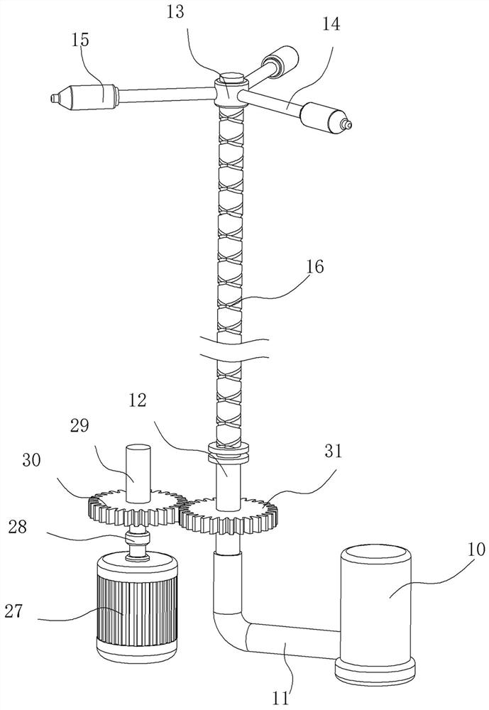
[0028] see figure 2 with image 3 , the spray assembly 8 in the figure includes a pump body 10 fixed in the liquid storage tank 4, the out...
Embodiment 2
[0033] Example 2: See Figure 4-Figure 7 Example 2 is described. This embodiment will further explain Example 1. In the illustration, the cleaning assembly 9 includes two sets of thread grooves 16 provided on the infusion tube 12. The thread directions of the two sets of thread grooves 16 are opposite, and the threads are connected with Threaded block 17, threaded groove 16 and threaded block 17 form a thread pair, and threaded block 17 can reciprocate up and down under the rotation of infusion tube 12, and the specific connection mode of infusion tube 12 and threaded block 17 is referring to the structure of reciprocating lead screw. The outer side of the threaded block 17 is fixedly connected with the first connecting rod 18 which is slidingly connected with the reactor 1, and the inner wall of the reactor 1 is provided with a first limiting groove 19 suitable for the first connecting rod 18, and the threaded block 17 The bottom end of the rotating ring 20 is connected with ...
Embodiment 3
[0035] Example 3: See Figure 8 Example 3 is described. This embodiment will further explain Example 1. In the illustration, the sealing assembly 7 includes a sealing plate 32 arranged at the bottom of the through hole 6. The sealing plate 32 is attached to the bottom of the reaction kettle 1, and the outside A slide rail 33 fixedly connected to the reaction kettle 1 is slidably connected, a support rod 34 is fixedly connected to the sealing plate 32, and a rack 35 meshing with the second flat gear 31 is fixedly connected to the support rod 34, and one end of the rack 35 Connect the limit piece 36;
[0036] see Figure 9 , the limiting member 36 in the figure includes a movable tooth 37 meshed with the second spur gear 31, the movable tooth 37 is fixedly connected with a first fixed seat 38, and the first fixed seat 38 is slidably connected with a connecting column 39, connected The column 39 is fixedly connected with the second fixed seat 40 fixedly connected with the rack ...
PUM
 Abstract
Description
Claims
Application Information
 - R&D
- Intellectual Property
- Life Sciences
- Materials
- Tech Scout
- Unparalleled Data Quality
- Higher Quality Content
- 60% Fewer Hallucinations
Browse by: Latest US Patents, China's latest patents, Technical Efficacy Thesaurus, Application Domain, Technology Topic, Popular Technical Reports.
© 2025 PatSnap. All rights reserved.Legal|Privacy policy|Modern Slavery Act Transparency Statement|Sitemap|About US| Contact US: help@patsnap.com