
Recovery unit for concrete block cutting process

A technology of concrete block and recycling device, which is applied to the removal of solid waste and other directions, can solve the problems of high cost of the device and increased workload of the waste storage tank inlet, and achieve the effect of reducing the workload.

Active Publication Date: 2018-12-25
重庆市泰日建材有限公司
View PDF5 Cites 0 Cited by
  • Summary
  • Abstract
  • Description
  • Claims
  • Application Information

AI Technical Summary

Problems solved by technology

[0005] The present invention intends to provide a recovery device used in the cutting process of concrete blocks, which is used to solve the problems that the existing recovery device cannot automatically clean the blocked waste storage tank inlet, which increases the workload and the problem of high device cost

Method used


Image

  • Recovery unit for concrete block cutting process
  • Recovery unit for concrete block cutting process

Examples


Embodiment Construction

[0022] The present invention will be described in further detail below by means of specific embodiments:

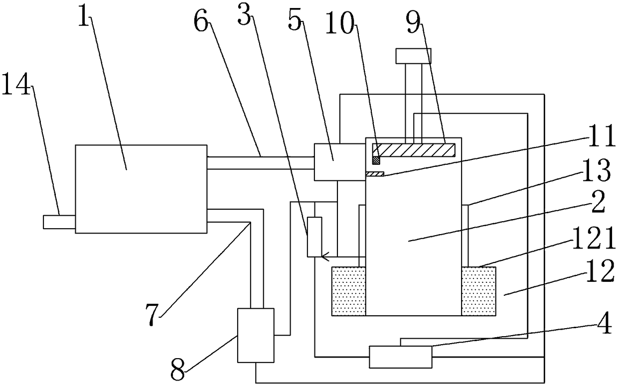
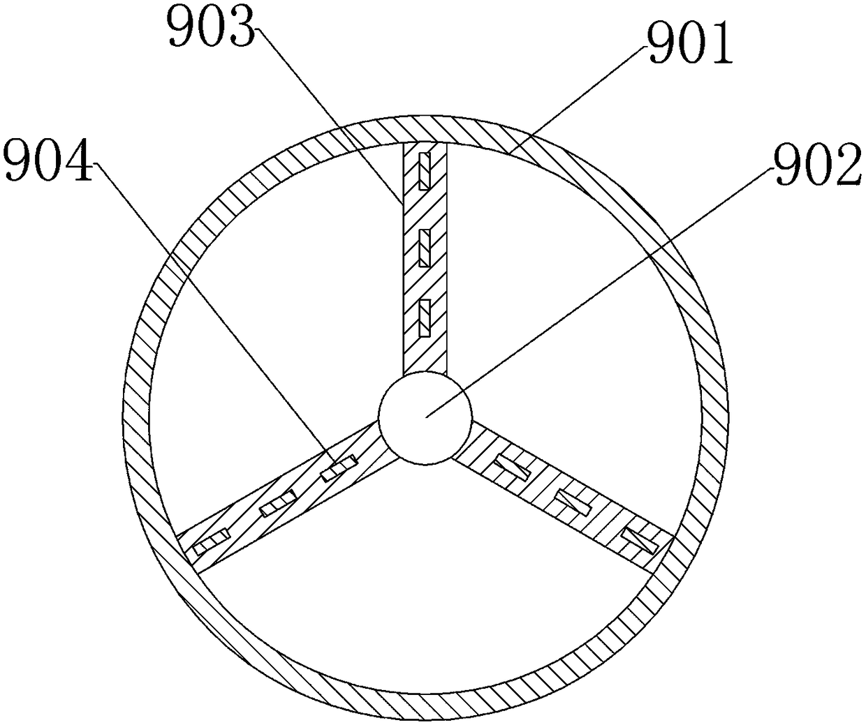
[0023] The reference signs in the accompanying drawings of the description include: grinding device 1, waste material collection tank 2, sliding rheostat 3, power supply 4, waste material lifter 5, feed pipeline 6, water inlet pipeline 7, water pump 8, crushing device 9, circle Shaped frame 901, rotating shaft 902, blade 903, cutter 904, self-resetting switch 10, operation panel 11, liquid storage tank 12, top plate 121, guide sleeve 13, discharge channel 14.

[0024] Example figure 1 and figure 2 As shown, it includes a grinding device 1 and a waste collection tank 2, and the grinding device is provided with a discharge channel 14, a feeding pipeline 6 and a water inlet pipeline 7 communicating therewith. An opening is provided on the top of the waste collection tank 2, and a waste lifter 5 is also provided. The waste lifter 5 is fixedly connected with the feed pipel...


PUM


Abstract

The invention relates to the technical field of concrete block machining, in particular to a recycling device used in the concrete block cutting process. Compared with the prior art, in the scheme, a waste elevator and a water suction pump are electrically connected with a power source through a slide rheostat, and the sliding end of the slide rheostat is fixedly connected with a waste collecting tank and further electrically connected with the fixed end, away from the power source, of the slide rheostat. The waste collecting tank is further provided with a crushing device electrically connected with the power source. The waste collecting tank is connected to the outer portion of the crushing device in a sleeving manner and is in sliding connection with the crushing device. A self-reset switch is arranged at the bottom of the crushing device. An operation panel corresponding to the self-reset switch is fixedly connected to the side wall of the waste collecting tank. A stirrer is arranged in the waste collecting tank, a liquid storage pond in which a solution is injected is arranged below the waste collecting tank, and the waste collecting tank is located in the liquid storage pond. The recycling device can solve the problems that an existing recycling device cannot automatically clean a blocked inlet of a waste storage tank, the workload is increased, and the device cost is high.

Description

technical field [0001] The invention relates to the technical field of concrete block processing, in particular to a recovery device used in the cutting process of concrete blocks. Background technique [0002] Concrete blocks are mainly used as the main building material, and its main raw material is mortar. The production of concrete blocks requires a series of steps such as mixing, forming, and cutting. During the cutting process, because the concrete block is not completely dry and the cutting knife has a strong vibration, a lot of waste materials of different sizes will be produced. Generally speaking, these waste materials will be discarded in the end, wasting resources, polluting the environment, and increasing the production cost of the enterprise. [0003] Therefore, the Chinese patent No. ZL201310377011.7 discloses a waste mortar recycling device for concrete blocks, including a mill, a sand conveying barrel, and a feeding chamber. The outlet of the sand conveyin...

Claims


Application Information

Patent Timeline
Patent Type & Authority Patents(China)
IPC IPC(8): B09B3/00
CPCB09B3/00
Inventor 林建涛
Owner 重庆市泰日建材有限公司
Learn More