A rotor of a disc permanent magnet motor and a disc permanent magnet motor using the same

A permanent magnet motor and rotor technology, applied in magnetic circuits, electromechanical devices, electrical components, etc., can solve the problems of wrong polarity of permanent magnets, motor damage, troublesome assembly process, etc. The effect of magnetism

Active Publication Date: 2022-07-15
ZHONGSHAN BROAD OCEAN
View PDF7 Cites 0 Cited by
  • Summary
  • Abstract
  • Description
  • Claims
  • Application Information

AI Technical Summary

Problems solved by technology

[0006] A further object of the present invention is to provide a rotor of a disc permanent magnet motor and a disc permanent magnet motor using it, so as to solve the problem that the magnetic fields of traditional built-in permanent magnet motors in the prior art are generally arranged in an N-S-N-S manner, with A closed-loop magnetic field is formed inside the rotor, which may easily lead to wrong polarity of the permanent magnet during assembly, resulting in damage to the motor and troublesome assembly process

Method used


Image

  • A rotor of a disc permanent magnet motor and a disc permanent magnet motor using the same
  • A rotor of a disc permanent magnet motor and a disc permanent magnet motor using the same
  • A rotor of a disc permanent magnet motor and a disc permanent magnet motor using the same

Examples


Embodiment 1

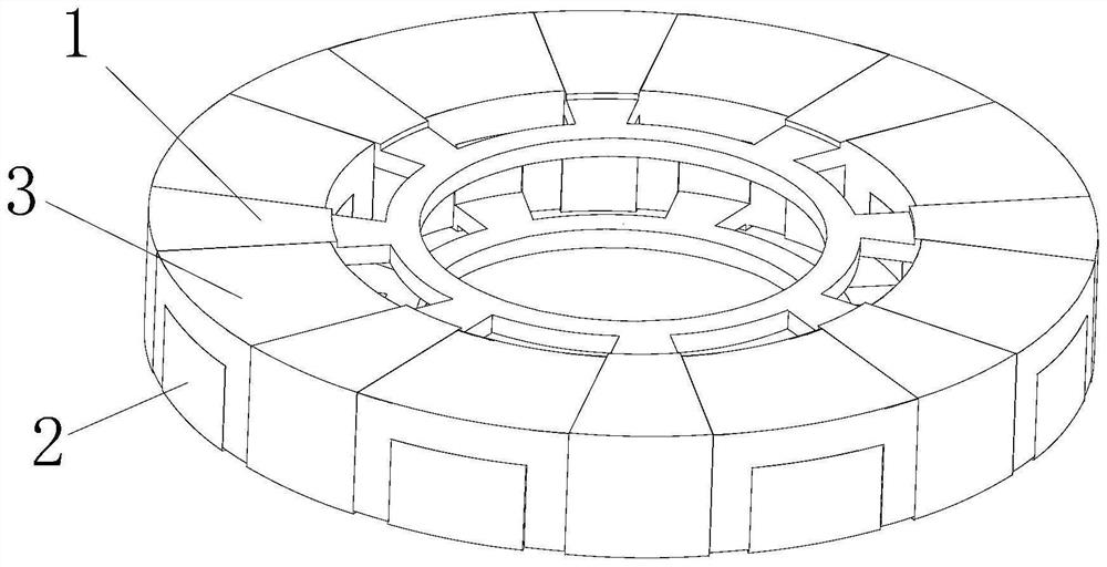
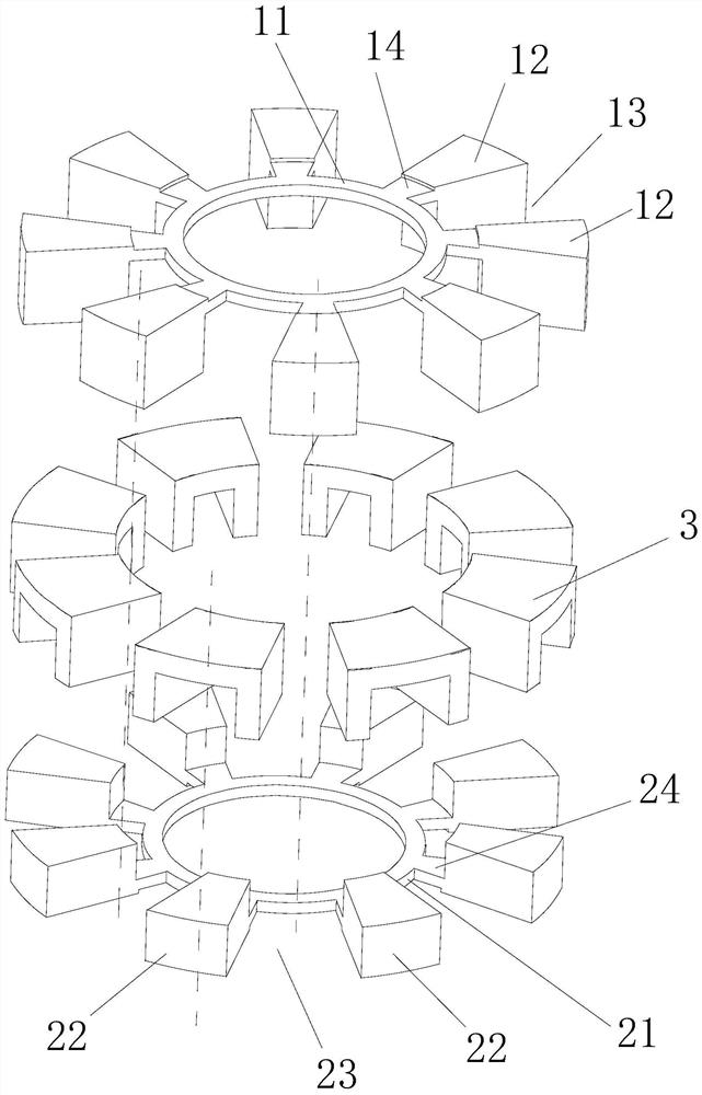
[0050] like Figure 2 to Figure 7 As shown, this embodiment provides a rotor of a disc permanent magnet motor, including a first rotor core 1, a second rotor core 2 and a number of magnetic tiles 3, and the first rotor core 1 includes a first annular ring 11 and several circumferentially spaced first magnetic conductive blocks 12 protruding from the outside of the first annular ring 11, a first groove 13 is formed between two adjacent first magnetic conductive blocks 12; the second rotor core 2. It includes a second annular ring 21 and a plurality of circumferentially spaced second magnetic conductive blocks 22 protruding from the outside of the second annular ring 21, and a second groove 23 is formed between two adjacent second magnetic conductive blocks 22. ; The first rotor core 1 and the second rotor core 2 are axially embedded, the first magnetic conductive block 12 is embedded in the second groove 23, and the second magnetic conductive block 22 is embedded in the first g...

Embodiment 2

[0059] like Figure 13 and Figure 14 As shown, this embodiment is modified on the basis of Embodiment 1. In this embodiment, the left magnetic steel 32 and the right magnetic steel 33 are inclined to the top magnetic steel 31, and the left magnetic steel 32 and the right magnetic steel 32 are inclined to the top magnetic steel 31. The angle formed between the magnet steel 33 and the top magnet steel 31 may be an obtuse angle or an acute angle.

Embodiment 3

[0061] like Figures 15 to 18 As shown, this embodiment is improved on the basis of Embodiment 1. In this embodiment, the top of the first magnetic conductive block 12 and the two sides of the first magnetic conductive block 12 are respectively convex. There is a first bump 5 , and the bottom surface of the first bump 5 abuts on the top surface of the magnetic tile 3 to limit the axial movement of the magnetic tile 3 ; The inner end portion 223 and the outer end portion 224 respectively protrude upward with second bumps 6 , the magnetic tile 3 is located between the two second bumps 6 , and the two second bumps 6 are used to limit The radial movement of the magnetic tile 3 can directly fix the magnetic tile 3 through the first bumps 5 and the second bumps 6, and does not need to be glued and fixed, which can simplify the assembly steps and improve the production efficiency.


PUM


Abstract

The invention discloses a rotor of a disk-type permanent magnet motor and a disk-type permanent magnet motor applying the same. The rotor includes a first rotor iron core, a second rotor iron core and a magnetic tile, and the first rotor iron core includes a first annular ring and the first magnetic conductive block, two adjacent first magnetic conductive blocks form a first groove; the second rotor core includes a second annular ring and a second magnetic conductive block, and two adjacent second magnetic conductive blocks form a second groove A left magnetic steel slot and a right magnetic steel slot are formed between the two sides of the second magnetic conductive block and the adjacent two first magnetic conductive blocks, and the first top surface of the second magnetic conductive block is lower than the phase The second top surfaces of the two first magnetic conductive blocks are adjacent to form the top surface magnetic steel groove; the magnetic tile includes the top magnetic steel, the left magnetic steel and the right magnetic steel, the top magnetic steel is embedded in the top magnetic steel groove, and the left magnetic steel is embedded in the top magnetic steel groove. The side magnet steel and the right magnet steel are embedded in the left magnet steel slot and the right magnet steel slot; the hybrid magnetization of the rotor is realized, the magnetization effect of the motor is improved, the number of assembled parts of the rotor is reduced, and the difficulty of the rotor manufacturing process is reduced. , improve the production efficiency of the rotor.

Description

Technical field: [0001] The invention relates to a rotor of a disc type permanent magnet motor and a disc type permanent magnet motor using the same. Background technique: [0002] The axial magnetic field disk-type permanent magnet synchronous motor in the prior art is used more and more because of its high power density, light weight and small size. In this existing motor structure, the rotor magnetic steel arrangement mostly adopts the surface-mounted magnetic steel structure axial magnetic field, but this surface-mounted axial magnetic field structure has the following shortcomings: First, in order to improve the air-gap magnetic flux density, It is necessary to increase the thickness of the surface-mounted magnetic steel, and the thickness is often increased by a large amount, and the air-gap magnetic flux density is not increased much, so the utilization rate of the magnetic steel is reduced; second, the inertia of the surface-mounted axial magnetic field structure mot...

Claims


Application Information

Patent Timeline
Patent Type & Authority Patents(China)
IPC IPC(8): H02K1/2795
CPCH02K1/2793H02K2213/03
Inventor 肖锐
Owner ZHONGSHAN BROAD OCEAN
Why Eureka
Try Eureka