[0036] It should be noted that the features of the present invention in the present invention may be combined with each other in the case of an unable conflict. The present invention will be described in detail below with reference to the accompanying drawings.
[0037] In order to make the objects, technical solutions, and advantages of the present invention more clearly, the technical solutions in the embodiments of the present invention will be described in contemplation in the embodiment of the present invention. It is merely the embodiment of the invention, not all of the embodiments. The following description of at least one exemplary embodiment is actually illustrative only, and it is not necessary to use any limitation of the invention and its application or use. Based on the embodiments of the present invention, all other embodiments obtained by those of ordinary skill in the art are in the range of the present invention without making creative labor premise.
[0038] It should be noted that the terms used herein are merely intended to describe embodiments, and is not intended to limit exemplary embodiments in accordance with the present invention. As used herein, unless the context further explicitly indicates that the singular form is intended to include multiple forms, but it should be understood that when the term "including" and / or "includes" in this specification, it indicates There is a combination of features, steps, operations, devices, components, and / or their combinations.
[0039] Unless otherwise specified, the counter arrangement, digital expression, and numerical values of the components and steps set forth in these examples do not limit the scope of the invention. At the same time, it should be understood that in order to facilitate the description, the dimensions of the respective portions shown in the drawings are not drawn in accordance with the actual ratio relationship. For those skilled in the art, methods and apparatus may not be discussed in detail, in appropriate, the techniques, methods and equipment should be considered part of the authorization manual. In all examples shown in and discussed herein, any specific value should be construed as is merely exemplary, not the limitation. Therefore, other examples of exemplary embodiments may have different values. It should be noted that similar reference numerals and letters represent the like items in the drawings below, and therefore, once a certain term is defined in one drawing, it is not necessary to discuss it in the following drawings.
[0040]In the description of the present invention, it is to be understood that orientation, such as "front, post, upper, lower, left, right", "horizontal, vertical, vertical, horizontal", and "top, bottom", etc. The orientation relationship is usually based on the orientation or positional relationship shown in the drawings, is merely intended to describe the present invention and the simplified description, these orientations do not indicate and imply the devices or components. It must have a specific orientation configuration and operation, so that it is not understood to limit the scope of the present invention: the orientation "Inner, external" refers to the inside and outside of the contour of each component itself.
[0041] To facilitate description, you can use space relative terms, such as "above ...", "in ...", "in ... upper surface", "above", etc., is used to describe as in the figure A device or feature of a device or a spatial position relationship between other devices or features. It should be understood that the space relative terminology is intended to include different orientations in use or operation in addition to the orientation of the device in the figure. For example, if the device in the drawings is inverted, it will be positioned as "above other devices or" above "or" above other devices or constructs ", it will be positioned as" in other devices or constructs "or" in " Its bit devices or under construction. " Thus, exemplary terms "above" can include "above" above "and" in ... below ". The device can also be positioned in different ways (rotation 90 degrees or other orientation), and will be explained in connection with the space used herein.
[0042] In addition, it is to be explained, using the words "first", "second" to limit the components, only to facilitate the difference of the corresponding components, if there is no separate declaration, the above words do not have special meanings, so it cannot be understood In order to limit the scope of the invention.
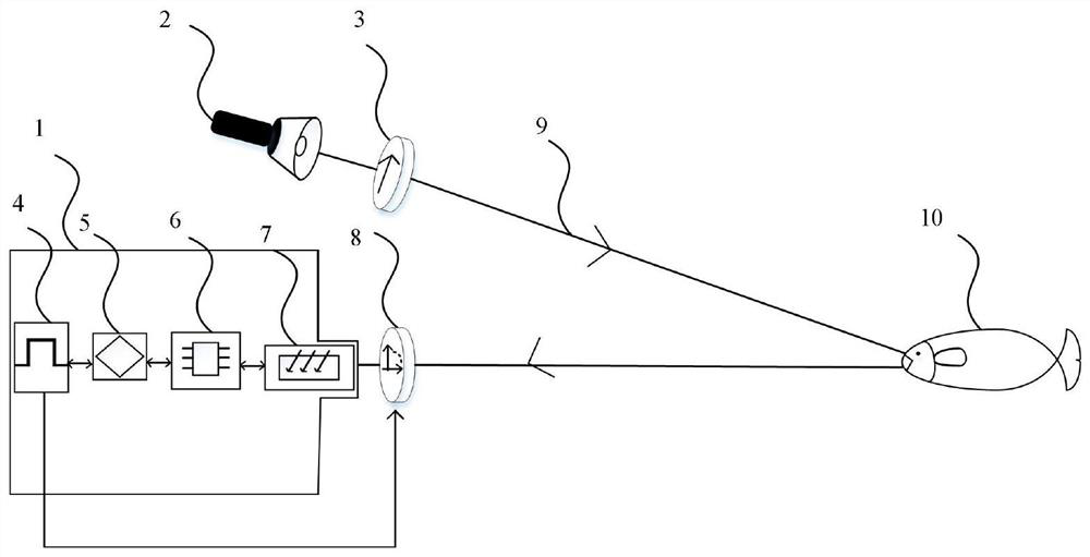
[0043] The present invention provides a technical solution: a real-time acquisition assembly and method for underwater differential polarization images, such as figure 1 As shown, the imaging unit 1 is provided, and the image unit 1 is provided with a light source 2, but the light source 2 is not unique. The light source 2 uses an LD (semiconductor laser), an LED (light emitting diode) or a halogen lamp. A linear polarizing plate 3 is provided in front of the light source 2, and the linear polarizing plate 3 is fixed in the polarization direction, and the light source 2 emits a fixed polarized light in the polarization direction by the linear polarizing plate 3. The electronically controlled polarization unit 8 is provided in front of the imaging unit 1, and the imaging unit 1 includes a high sensitivity image sensor 7, an MCU (microcontroller) 6, the synchronous circuit 4, and the image pre-processing module 5, the high sensitivity image sensor 7 is suitable for underwater visibility. Shooting in a low environment; the image sensor 7 uses a surface channel metal oxide semiconductor, an electronic multiplier charge coupling device or ICCD. The microcontroller 6 acquires the signal output from the image sensor 7, the synchronous circuit 4 connects the microcontroller 6 and the electronically controlled polarization unit 8 to change the polarization state of the electrically controlled polarization unit 8, and the image pre-processing module 5 receives the captured. Picture of different polarization is processed as a DOP (polarization) image.
[0044] The light source 2 emits polarized light to the target object, and the target object reflects light into the camera lens through the insulator, and converts the electrical signal, the MCU collects the electrical signal, the MCU control synchronization circuit 4 output by the camera internal image sensor 7. The synchronization signal is delivered to the electronically controlled polarization unit 8, and the electronically controlled polarization unit 8 is changed in real time, and the picture of different polarizers is collected. The MCU Control Image Pre-Processing Module 5 calculates the output of different partial radiological states and outputs the corresponding DOP image.
[0045] The microcontroller 6 issues a control signal to control the electronically controlled polarization unit 8 polarized state transformation, including three acquisition differential polarization image modes:
[0046] Four matrix state: The electronically controlled polarization unit 8 has four linear polarized states, and the four polarization states are referenced by the initial polarization state rotation angle, respectively rotate 0 °, 45 °, 90 ° and 135 °, respectively;
[0047] Double linear polarization state: The electronically controlled polarization unit 8 has two linear polarizers, and the two polarization states are referenced by the initial polarization state rotation angle, respectively rotate 0 ° and 90 °, and improve the taking image efficiency;
[0048] Double circular biasing state: The electronically controlled polarization unit 8 has two circularly polarized state, which is a left radius polarization state and a right-rotator polarization state.
[0049] Real-time acquisition method for underwater differential polarization images, including the following steps:
[0050] S1, select the acquisition differential polarization image mode:
[0051] When the four-polarization state mode is selected, the microcontroller 6 controls the image sensor 7 exposing, the synchronization circuit 4 outputs the synchronization signal to the electrical control polarization unit 8, the electronically controlled polarization unit 8 accepts the synchronization signal, changing the polarization state, and obtains four different polarization states Image, output differential polarization images in units of these four polarization images;
[0052] When the double linear polarization state mode is selected, the microcontroller 6 controls the image sensor 7 exposing, the synchronization circuit 4 outputs the synchronization signal to the electrically controlled polarization unit 8, the electronically controlled polarization unit 8 receives the synchronization signal, changing the polarization state, and two different Picture of polarized state, output differential polarization images in units of two polarized images;
[0053] When the double-circular polarization state mode is selected, a 1/4 wave plate is added after the electronically controlled polarization unit 8, so that the linear polarization light by the electronically controlled polarization unit 8 is changed to a circular polarity light, the microcontroller 6 controls the image sensor 7 exposure. The synchronous circuit 4 outputs a synchronization signal to the electrical control polarization unit 8, the electronically controlled polarization unit 8 accepts the synchronization signal, changing the polarization state, to obtain a circular polarizing picture having different rotational elements, and output differential polarization images in units of two polarization images. ;
[0054] S2, transmit differential polarization images to the image pre-processing module 5, select the corresponding formula according to the differential polarization image mode selected by S1, to obtain a DOP picture;
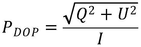
[0055] When the differential polarization image mode is a quadruple state or birenular polarization state, DOP image is obtained according to the following formula:
[0056]
[0057] When the differential polarization image mode is a double-circular polarization state, the DOP diagram is obtained according to the following formula:
[0058]
[0059] Wherein, i represents the strength of the light, Q represents the difference between the intensity of the 0 ° to 90 ° polarization direction, and U represents the intensity difference of the light in the polarization direction of 45 ° to 135 °.
[0060] S3, the imaging unit 1 outputs a DOP image, completes an imaging process, and rotates to S1 until all imaging processes are completed.
[0061] The operation mode is used as an example: the light source 2 emits light, and is irradiated along the transmission path 9 to the target 10, the target 10 reflects light into the imaging unit 1, the image sensor 7 sensor, generates an electrical signal. The MCU 6 transmits signals to the synchronous circuit 4, and the synchronous circuit 4 is in the polarization direction of the electric control polarizing plate 8 in the polarization direction of 0 °, the camera exposure, and acquires the initial state picture. The MCU6 outputs the picture to the image pre-processing module 5 after the camera collects pictures, and the image pre-processing module 5 is temporarily stored. The MCU 5 transmits signals to the synchronous circuit 4, and the synchronization circuit 4 causes a picture of the electrically controlled polarizing plate 8 in the polarization direction of 45 °, camera exposure, and collecting a polarization direction 45 °. The MCU6 outputs the picture to the image pre-processing module 5 after the camera collects pictures, and the image pre-processing module 5 is temporarily present. The MCU6 transmits signals to the synchronous circuit 4, and the synchronization circuit 4 is in the polarization direction of the electronically controlled polarizing plate 8 at 90 °, the camera exposure, and collects a picture of 90 ° in the polarization direction. The MCU6 outputs the picture to the image pre-processing module 5 after the camera acquires pictures, and the image pre-processing module 5 is temporarily present. The MCU6 transmits signals to the synchronous circuit 4, and the synchronous circuit 4 causes a picture of the electronically controlled polarizing plate 8 in polarization direction at 135 °, the camera exposure, and collects 135 ° in the polarization direction. The MCU6 outputs the picture to the image pre-processing module 5 after the camera is acquired, and the image pre-processing module 5 is temporarily stored, and the four polarizational states are different. The pre-processing module 5 calculates the four picture components of the four images in pixels, calculates DOP according to the formula until all the cells are completed, and the calculation process is completed, and the DOP picture is output. When the operation mode is two linear polarizers, two polarized states are different, and the image pre-processing module 5 calculates the Stokes component of these two pictures in pixels. The DOP is calculated according to the formula until the completion of all the like metals. , Complete the calculation process, output the DOP picture; when the operation mode is two round-polarizes, the two polarized splitters are different, the image pre-processing module 5 calculates the two pictures of Stokes components in units of pixels. The DOP is calculated according to the formula until the completion of all pixels, complete the calculation process, and output the DOP image. Since the two linear polarization states are the same as the overall process of two circularly polarized state operations, they will not be described again.
[0062] In this specific embodiment, the synchronous circuit 4 transmits a synchronous signal to the electronically controlled polarizing plate 8, and the electronically controlled polarizing plate 8 is polarized. like figure 2 As shown, when the timing logic changes in the camera's timing diagram, the synchronous circuit 4 controls the electronically controlled polarizing plate 8 to change the timing of the electric control bile pad as the camera timing. When the camera timing experiences periodically, when the sequence unit falls, the electronically controlled polarizing plate 8 has a change in electronically polarized state. When the camera unit experiences the first timing falling edge, the electronically controlled polarization timing is started to change until stable. At this time, the polarization state is set to 0 °; at the next time at the next time, the polarization state starts to change until Stable, at this time, the polarization state is 45 °; this step performs periodic repeat until all of the polarization is taken after all polarization states.
[0063] As described above, only the preferred embodiments of the present invention are preferred, but the scope of the invention is not limited thereto, and any technicress, those skilled in the art, in accordance with the technical solution according to the present invention. And the inventive concept is equivalent to alternative or change, and it should be covered within the scope of the invention.