

Method for determining user plane function and providing information, equipment and medium
A user interface and application function technology, applied in wireless communication, electrical components, etc., can solve problems such as non-optimal solutions, and achieve the effect of ensuring user experience and business performance
- Summary
- Abstract
- Description
- Claims
- Application Information
AI Technical Summary
Problems solved by technology
Method used
Image

Examples
Embodiment 1
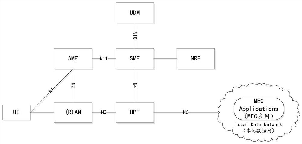
[0457] This example illustrates the implementation of NWDAF collecting data and generating user experience analysis of EC Application.
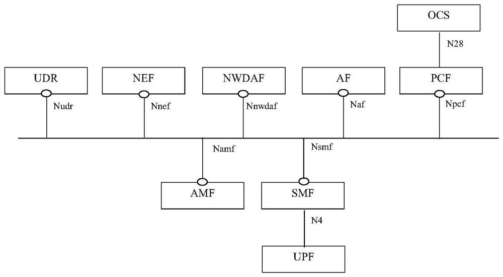
[0458] In order to generate a user experience analysis of EC Application deployed on the 3GPP network, NWDAF can collect relevant data from SMF and AF.
[0459] Data collected from SMF may include:
[0460]
[0461] Data collected from AF can include:
[0462]
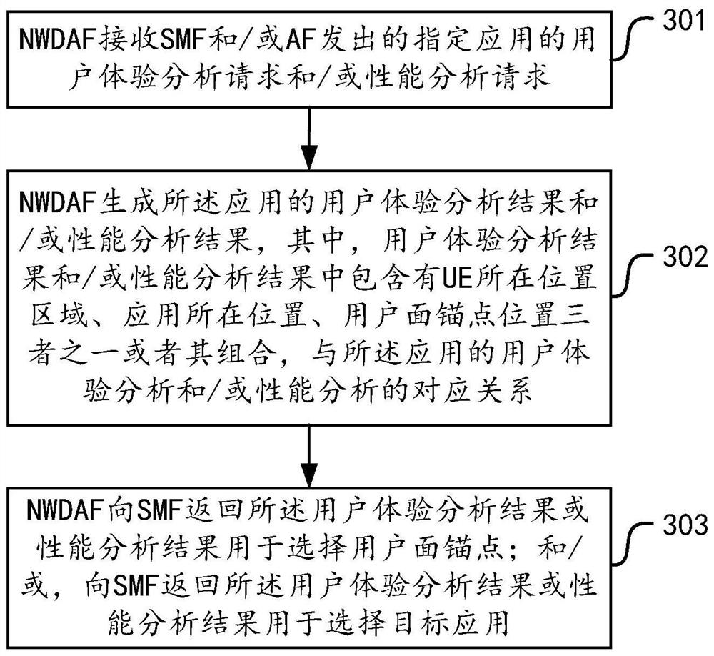
[0463] NWDAF can correlate the data collected from SMF with the data collected from AF through timestamp and IP filter information. NWDAF uses machine learning algorithms to mine out the relationship between data, and the generated data analysis results can include the following:
[0464] Table 1: User experience analysis of EC Application (> indicates that there is an inclusion relationship between these table items)
[0465]
Embodiment 2
[0467] This example illustrates the implementation of NWDAF providing SMF with user experience analysis of each EC Application.
[0468] The data analysis content provided by NWDAF includes the content in Table 1. In addition, if the SMF requests user experience analysis, it can also request the NWDAF to directly provide Anchor UPF (anchor UPF) recommendation information that can guarantee user experience or service performance.
[0469] Figure 6 It is a schematic flow diagram of the NWDAF providing data analysis results to the SMF in Embodiment 2. As shown in the figure, based on the analysis provided by the NWDAF, the SMF can optimize the user plane path when the UE accesses the edge computing application. The flow can be as follows:
[0470] Step 601, PDU Session is established.
[0471] The UE creates a PDU session, and the carried S-NSSAI (Single-NetworkSlice Selection Assistance Information, Single-NetworkSlice Selection Assistance Information) and DNN indicate that t...
Embodiment 3
[0495] This example illustrates the implementation of NWDAF providing EC Application user experience analysis to AF.
[0496] The data analysis content provided by NWDAF includes the following:
[0497] Table 2: User experience analysis of EC Application (> indicates that there is an inclusion relationship between these table items)
[0498]
[0499] In addition, if the AF requests user experience analysis, it can also request the NWDAF to provide DNAI recommendation information that can guarantee user experience / service performance.
[0500] Figure 7 It is a schematic flow diagram of the NWDAF providing data analysis results to the AF in Embodiment 3. As shown in the figure, based on the analysis provided by the NWDAF, the AF can determine the optimal application server when the UE accesses the edge computing application. The flow can be as follows:
[0501] Step 701, PDU Session is established.
[0502] Step 702, Data Traffic.
[0503] The UE creates a PDU session, a...
PUM
 Abstract
Description
Claims
Application Information