
Dust removal system for building engineering construction

A dust removal system and construction engineering technology, applied in construction, use of liquid separating agent, and filtration of dispersed particles, can solve problems such as high cost of use, increased water consumption, and difficult adjustment of the amount of water mist sprayed from the spray cylinder, etc., to achieve Good dust removal effect

Pending Publication Date: 2021-11-05
邬晏初
View PDF1 Cites 1 Cited by
  • Summary
  • Abstract
  • Description
  • Claims
  • Application Information

AI Technical Summary

Problems solved by technology

[0005] First, the dust removal effect is not good, because it only reduces the dust in the air at the construction area by spraying water mist and combining with the dust in the air to make it settle, but the total amount of dust at the construction area will not be reduced ( It will even increase), which makes the above-mentioned devices need to work frequently and for a long time to ensure that the air quality in the construction area is always up to standard (the wet dust will float into the air in the construction area again after drying)
[0006] Second, the use cost is high, because the situation of dust generation in different areas on the construction site is different, so special personnel are required to manually push the above-mentioned device to move to the designated area for dust removal (workers are also required to adjust the spray cylinder to the optimum Spray angle), at the same time, the amount of water mist sprayed by the spray cylinder is not easy to adjust according to the actual situation, thus increasing the water consumption

Method used


Image

  • Dust removal system for building engineering construction
  • Dust removal system for building engineering construction
  • Dust removal system for building engineering construction

Examples


Embodiment

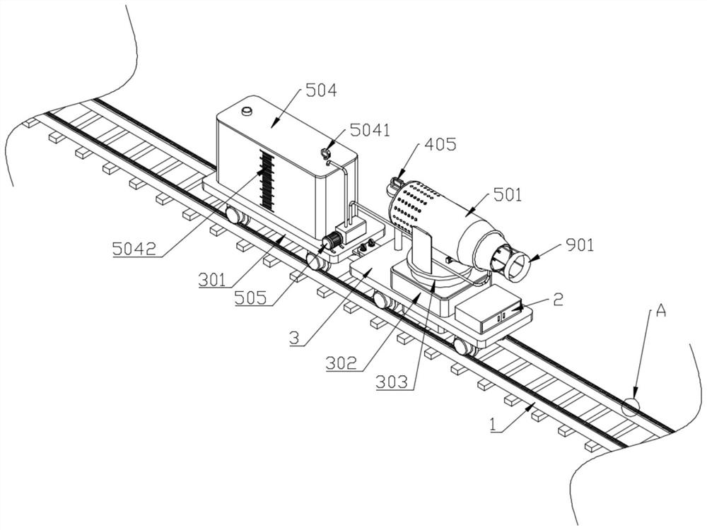
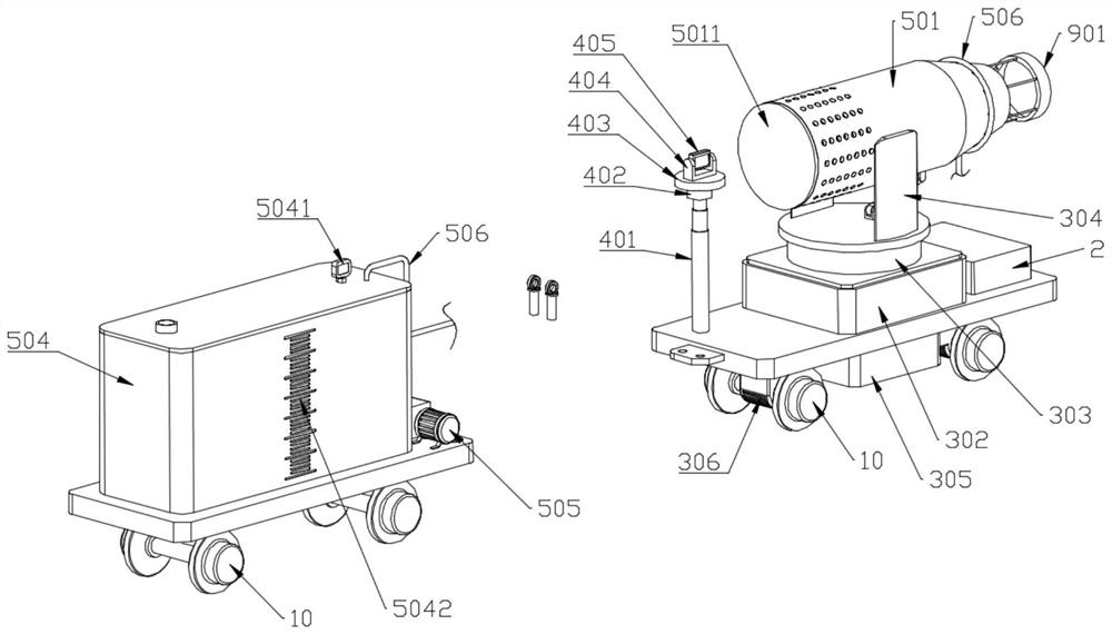
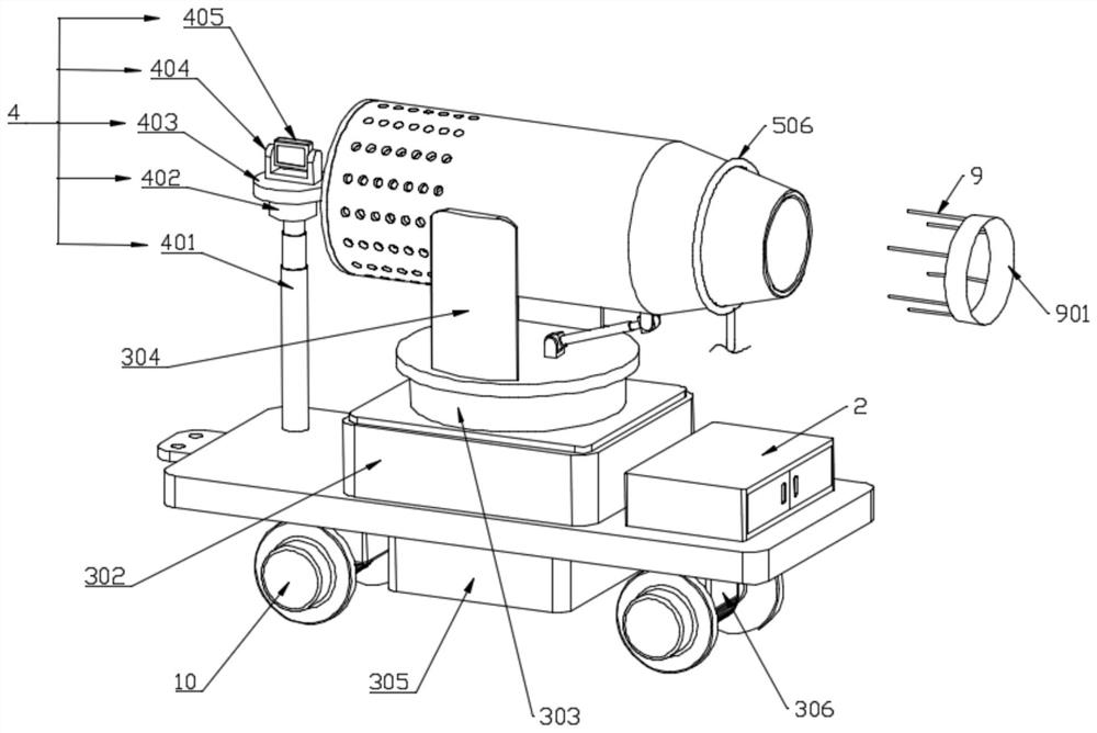
[0062] This embodiment provides a kind of dust removal system for building engineering construction, with reference to Figure 1-14 : Including track 1, vehicle assembly, purification assembly and PLC control box 2.

[0063] It should be noted that the PLC control box 2 is set on the tractor 3 , and the electrical components in the present invention are all controlled by the PLC control box 2 and powered by the battery 305 .

[0064] Track 1 is pre-laid on the ground in the specified path. Because the complex working conditions of the construction site will make the surface of the track 1 become wet, so that the tractor 3 and the trailer 301 will slip when they are running on the track 1 (or the tractor 3 and the trailer 301 will be parked on the track 1) (In addition, when the fog cannon assembly 5 sprays water mist, there is a possibility that the track 1 will become wet); therefore, it is necessary to evenly arrange the anti-slip embossing 101 on the surface of the track 1...


PUM

PropertyMeasurementUnit
Critical temperatureaaaaaaaaaa

Abstract

The invention relates to the technical field of building engineering, in particular to a dust removal system for building engineering construction. The dust removal system comprises a track, a carrier assembly, a purification assembly and a PLC control box, wherein the carrier assembly comprises a tractor and a trailer which run on the track; the purification assembly comprises a fog gun assembly and a dust removal assembly; the fog gun assembly comprises a conical pipe, a turbofan, a set of atomizers, a water storage tank and a water pump; the dust removal assembly comprises a filter plate, a dust collection box, a negative pressure pump and a sweeping assembly; the PLC control box is arranged on the tractor; the carrier assembly, a detection assembly, a driving assembly and the purification assembly are all controlled by the PLC control box and powered by a storage battery; and the sweeping assembly comprises an I-shaped arm, a cross arm and a brush body. The problems of poor dust removal effect, high use cost and the like in the prior art can be effectively solved.

Description

technical field [0001] The invention relates to the technical field of building engineering, in particular to a dust removal system for building engineering construction. Background technique [0002] During the construction process of the construction site, due to the outdoor working environment, the dust on the construction site is rolled up with the driving of the motor vehicle. Therefore, the use of dust removal equipment on the construction site is very common; but the dust removal equipment used in construction projects now, Its spray structure is only a cylindrical structure, which is directly blown by the fan to spray water mist during use. [0003] In the patent document with the application number CN202022372132.0, an environmental protection dust removal equipment for construction engineering is disclosed, which includes a main base, a water tank installed on the main base, a water pump and a hydraulic cylinder, and a rotating base connected to the top of the hydr...

Claims


Application Information

Patent Timeline
IPC IPC(8): B01D50/00B01D46/10B01D47/06E01H3/02
CPCB01D46/10B01D47/06E01H3/02
Inventor 邬晏初
Owner 邬晏初
Learn More